Soffit Weathering Bay & Bow Windows – Foshan Price
1. System Overview — The Bay Is a Volume Bolted to a Building, and Most of Its Surfaces Are Not Windows
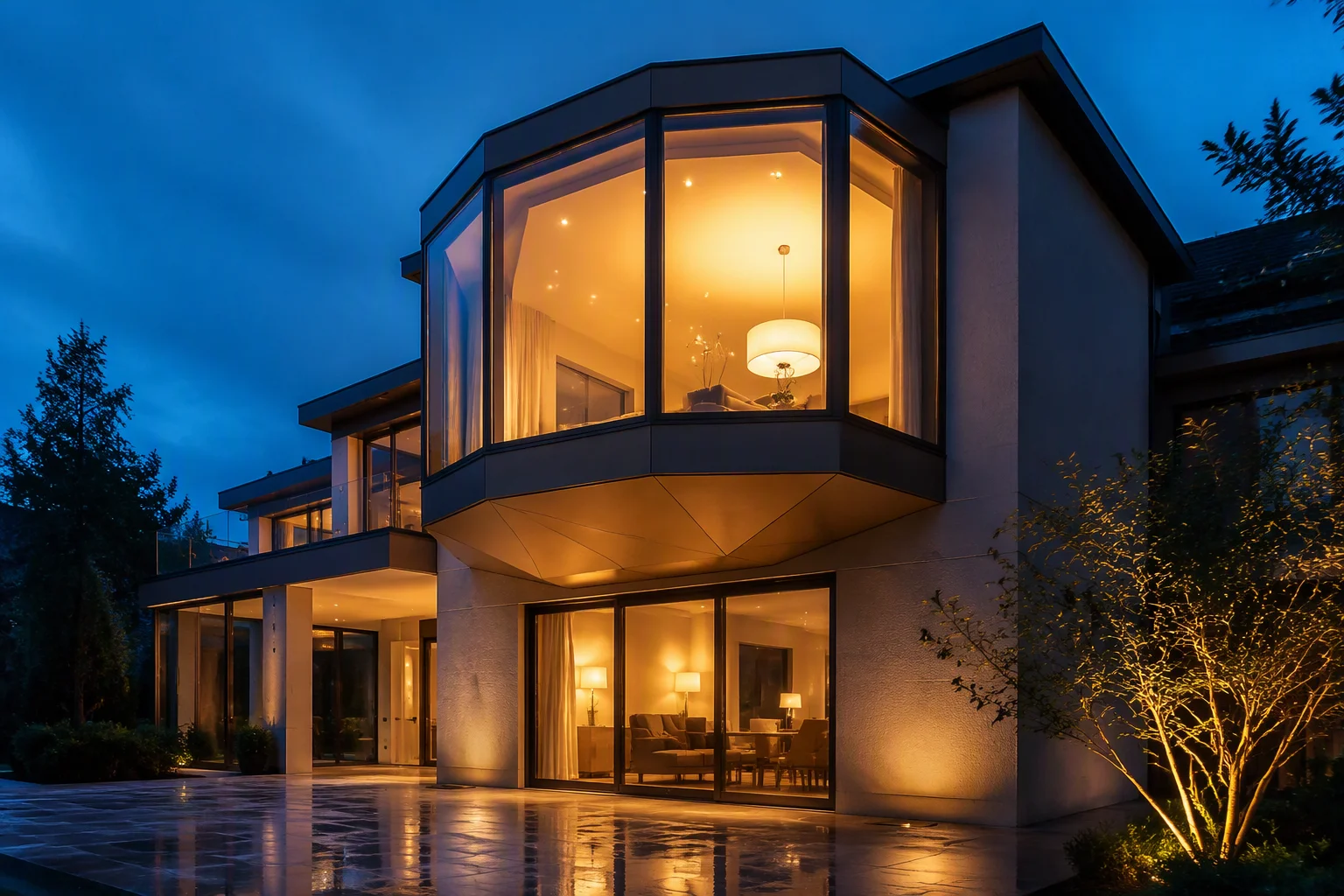
A flat window is a hole in the building envelope that has been filled with a component. A bay or bow window is not that. It is a volume that has been added to the building — a three-dimensional room-sized or chair-sized box that stands outside the plane of the wall, connected to the structure along one face and exposed to the weather on the other five. That distinction is not a matter of description; it determines where the product fails, who is responsible for each of its surfaces, and what a specification has to say in order for the thing to work. Because a flat window has one plane and that plane is the window, everything about it falls inside the window class system: the air permeability, the watertightness, the wind resistance, the thermal transmittance, the acoustic rating, all measured on that one plane, all delivered by one supplier, all warranted by one document. A bay has six surfaces and only some of them are windows.
Enumerate them and the problem becomes visible. The glazed facets — two, three, five or more angled planes of glass in frames — are windows, and they fall inside the class system. The corner posts between them are window components, and they are structural ones, which is a point dealt with elsewhere and not repeated here. The head, or top surface, is a roof: a horizontal or low-sloped plane, exposed to rain, snow, ultraviolet, freeze-thaw, leaf fall and bird droppings, with a falls, a waterproofing layer or metal flashing, an upstand where it meets the main wall, an edge detail and often a gutter or a drip — designed and warranted as a roof, exposed as a roof, and reaching the end of its service life on a roof’s timetable rather than a window’s. The soffit, or underside, is the exposed lower face of a cantilevered slab: horizontal, facing downward, receiving no solar gain, sitting in a turbulent recirculating airflow directly beneath a projection, and — thermally — the other side of the interior window board that people sit on or put plants on. The two vertical sides where the bay meets the main wall are not window joints at all: they are movement joints between two building systems, one of which is a cantilevered volume that deflects under load and expands with temperature, and the other of which is a wall that does neither in the same way or at the same rate. And the interior volume enclosed by all of this is a space that protrudes beyond the building’s thermal envelope, is usually not served by heating or cooling, is usually occupied by a seat or a shelf, and is usually the coldest place in the room.
So the honest summary is this: a bay or bow window is a product whose specification, warranty and maintenance regime have to cover at least four different building systems — a window, a roof, a cantilevered slab, and a movement joint — plus an unconditioned semi-exterior space. And in practice it is usually procured as a window. That single mismatch between what the product is and how it is bought is the origin of most of the failures reported against bay and bow installations: water entering at the head flashing, which is a roof failure attributed to a window supplier; mould on the interior window board, which is a two-dimensional thermal bridge through a site-built slab that nobody calculated; a crack in the corner sealant joint, which is a movement joint failure caused by long-term deflection of a support that was designed for strength and not for deformation; and a rattling or leaking facet, which is the only one of those that is actually a window failure. The specification has to name each surface and say which system it belongs to, which supplier provides it, which standard governs it, and who inspects it — because a surface that belongs to nobody is a surface that fails.
Richocean manufactures thermally broken aluminium bay and bow window units in Foshan, Guangdong — 6063-T6 facet frames and corner posts with PA66GF25 polyamide breaks, angular bay geometries with factory-finished corner posts and continuous bow geometries approximated by multi-plane facets or formed from genuinely curved sections and glass, integrated head and soffit cassettes where the package is supplied as a complete volume rather than as windows alone, laminated and insulating low-iron glass specified for the angled facets’ edge conditions, stainless hardware for the exposed faces, and factory-applied flashings and upstands designed to mate with a stated main-wall build-up — for residences, hotels, restaurants, apartments and heritage-adjacent new build across Europe, the Middle East, North America, Southeast Asia and coastal markets, with each package documented surface by surface: which faces are windows and which are not, who supplies and who accepts each, the head’s falls and flashing arrangement and its upstand into the main wall, the soffit’s thermal bridge and its interior surface temperature, the movement joint’s width and displacement rating, the deflection limit set by the sealant and the glass rather than by the structure, the developed glass area against the aperture area it replaces, the internal volume’s service and its condensation risk, and the escape provision measured on the facet rather than assumed from the aperture.
2. Six Surfaces, and Only Some of Them Fall Inside the Window Class System
The window class system is organised around a plane. Air permeability on the EN 12207 basis measures how much air passes through a closed window per unit of its area at a stated pressure difference. Watertightness on the EN 12208 basis measures the pressure at which water passes through it. Wind resistance on the EN 12210 and EN 12211 bases measures its deflection and its resistance to a pressure applied perpendicular to that plane. Thermal transmittance on the EN ISO 10077 basis measures heat flow through it. Acoustic performance on the EN ISO 10140 and 717-1 bases measures sound reduction across it. Every one of those is a property of a plane, tested on a plane, and quoted for a plane. That is entirely correct for a flat window, because a flat window is a plane.
It is not correct for a bay, and the reason is geometric rather than a matter of test method. A bay’s surfaces do not all lie in one plane, do not all face the same direction, and are not all exposed to the same environment. The facets are inclined, so a pressure perpendicular to the wall is not perpendicular to them and a pressure perpendicular to them is not perpendicular to the wall — which means the facet’s class and the assembly’s behaviour in the wall’s wind field are two different quantities, and quoting the former says nothing about the latter. The head is horizontal, so it is not loaded by wind in the way a vertical plane is; it is loaded by rain falling on it, by snow lying on it, and by water running across it, and its performance is a waterproofing performance rather than a watertightness-under-pressure performance, which is a different test with a different failure criterion. The soffit is horizontal and faces downward, so it never sees rain falling on it, but it sees driven rain arriving from below in the turbulent zone under the projection, it sees no solar gain at all, and it is the cold face of a thermal bridge. The sides are vertical but they are not windows — they are the junction between the bay and the main wall, and their performance is a movement joint’s performance: a width, a sealant with a stated movement capability, a backing rod, a bond-breaker, and a drainage path, none of which appears in any window standard.
So a bay’s specification has to be written surface by surface, with the governing system named for each, and with the interfaces between them named as well, because the interfaces are where the failures concentrate. The head-to-wall interface is a flashing detail and an upstand, and it belongs to the roofing system, and it has to be accepted by whoever accepts the roof. The head-to-facet interface is where the roofing layer meets the top of the window frame, and it belongs to neither system cleanly — which is precisely why it leaks, and precisely why it has to be assigned explicitly rather than left to be discovered on site. The soffit-to-facet interface is where the underside meets the bottom of the glass, and it is a drainage and a thermal question at once. The side-to-wall interface is a movement joint and belongs to the facade’s jointing system. And the soffit-to-interior interface is where the cantilevered slab meets the interior window board, and it is a thermal bridge question that belongs to nobody at all unless someone is assigned it, which is why the mould appears there.
Two consequences follow for procurement, and both are commercial rather than technical. The first is that a bay’s service life is set by its shortest-lived surface and that surface is usually not the window. The aluminium frames and the insulating glass will last decades; the head’s waterproofing layer or metal flashing will not, because it is horizontal, exposed, ultraviolet-loaded, thermally cycled, and — decisively — unreachable from inside and usually unreachable from outside without access equipment. So a bay has to be designed for its head to be replaced, which means the head detail has to allow a flashing to be lifted and re-laid without dismantling the windows below it, and that requirement has to be stated before the section is drawn, because it cannot be retrofitted. The second is that a bay’s warranty cannot be a window warranty. A window warranty covers the component; a bay needs the component’s performance plus the roof’s, plus the slab’s thermal behaviour, plus the movement joint’s, plus a statement of who is responsible for each. Where the factory supplies only the windows and the head and soffit are built on site by others, the warranty boundary has to be drawn explicitly and the interfaces have to be detailed by agreement rather than by assumption — and the single most valuable document in that arrangement is not a test certificate but an interface drawing that both parties have signed.
3. The Head Is a Roof, and It Is Procured as a Window
Take the top surface of a projecting bay seriously, as a roofing professional would, and the list of things it has to do is long. It has to shed water, which means it has to have falls — a minimum slope, in a stated direction, to a stated outlet or over a stated edge — because a genuinely flat head is a ponding head, and ponded water finds every defect that a drained surface would never have to reveal. It has to have a waterproofing layer or a metal covering, with a stated material, a stated thickness or gauge, and a stated method of joining the sheets or seams, because the joints are where water enters and a monolithic-looking metal head is not monolithic: it is panels with laps, welds, folds or sealant beads, each with its own life. It has to have an upstand where it meets the main wall — a vertical return, of a stated height above the finished surface, so that water running down the wall is not presented with a horizontal surface to enter at the exact line where two systems meet. It has to have an edge detail — a drip, a fascia, a gutter or a thrown edge — that gets the water clear of the soffit below, because water that runs back under the head runs down the facets, and water that runs off the edge without a drip tracks back underneath and arrives on the soffit and the glass. And it has to survive being horizontal, exposed, unreached and uncleaned: leaf fall, moss, bird droppings, wind-borne grit, standing water in winter, thermal cycling between a sun-heated surface and a night-cooled one, ultraviolet degradation of any polymeric component, and — in a snowy climate — the load of snow that has drifted against the wall above it and the ice dam that forms at its cold edge.
Every one of those is a roofing requirement, and not one of them appears in a window standard. Which is why the head of a bay window fails on a roofing timetable and is blamed on a window product. The typical sequence is instructive. The head is built on site, or supplied as a metal tray, and the upstand is made good against the main wall’s waterproofing or against its render, at a moment when the wall’s own trades are still working and the detail is improvised rather than drawn. Water enters at the upstand — because the render cracks, because the sealant loses adhesion to a dusty substrate, because the upstand is shorter than the height to which wind-driven rain climbs the wall, or because the fall is insufficient and water stands against the upstand for hours instead of leaving in minutes. It enters above the ceiling line of the bay’s interior, so it travels along the head’s structure, past the insulation, and appears as a stain on the interior soffit or on the wall beside the bay — nowhere near where it entered. By then the sealant has been in place for years, the defect is inside a construction nobody can inspect without opening it, and the diagnosis is guesswork. That sequence is avoidable, and avoiding it is a matter of assigning the head to the roofing system in the specification, drawing the upstand and the fall rather than describing them, and insisting that the head can be inspected and re-waterproofed without dismantling the windows below.
There is a second head question that is specific to bays and has no flat-window analogue: what happens to the water that leaves the head. On a flat window, rain runs down the glass and out over the sill’s drip. On a bay, rain runs off the head and arrives on the facets below — which are windows, which are therefore being subjected to a concentrated flow along their top edge rather than a distributed flow across their face, and which have to shed it. That means the facet’s head detail has to handle a water load that the same window would not see if it were installed flat in a wall, and it means the head’s edge detail is a design object rather than a trim: a thrown edge or a drip that projects the water clear of the facets does a different job from a fascia that returns it to the glass. Where a gutter is used, the gutter is a roof gutter — sized for the head’s catchment area, which on a projecting bay is larger than its plan area suggests because it also catches water running down the main wall above it, and which therefore has to be computed rather than selected by eye. And where the head is a metal tray, its thermal behaviour matters too, because a metal tray bridging from the exterior to the interior at the top of the bay is a linear thermal bridge that will condense on the inside face in cold weather, in a place where nobody expects condensation because it is above the glass rather than at it.
The commercial consequence for a factory exporting bays is the interface question, and it has to be answered before an order is taken rather than after a claim is made. Either the head is supplied as part of the unit — a factory-finished cassette with its falls, its covering, its upstand and its edge detail, designed to mate with a stated main-wall build-up, with the mating condition drawn and warranted — or it is built on site by others, in which case the factory’s scope stops at the top of its frame and the responsibility for everything above that line belongs to whoever builds it, and that boundary has to be written down and signed. The first arrangement is more expensive and far more reliable, because it makes one party responsible for a complete waterproofing system. The second is cheaper at tender and generates claims, because the interface between a factory frame and a site-built head is exactly the place where two trades, two materials, two programmes and two warranties meet, and it is where the water enters. Neither is wrong, but the choice has to be made explicitly, and a specification that does not make it has made it by default — and the default is usually the second.
4. The Junction with the Main Wall Is a Movement Joint Between Two Building Systems, Not a Window-to-Opening Joint
A flat window is installed into an opening. The opening has a tolerance, the frame has a tolerance, and the difference is absorbed by packers, by a perimeter joint of a stated width filled with a compressible backing and a sealant, and by a sill arrangement that drains whatever arrives. The joint moves because the frame moves thermally and because the structure moves slightly, and its movement is small: a window frame’s thermal expansion over its own length, plus the building’s seasonal movement, both measured in single-digit millimetres on a typical domestic size. That is a window joint, and window jointing practice handles it.
A bay’s junction with the main wall is a different thing. One side of it is a wall: massive, slow-moving, tied into the building’s structure, with its own render or cladding and its own waterproofing layer. The other side is a projection: a volume standing outside the wall plane, supported by brackets, by a cantilevered slab, by suspension from above, or by a structural sill, carrying its own weight plus snow plus wind plus the weight of anyone who leans on it, deflecting under those loads, expanding and contracting with its own thermal history — which is not the wall’s, because the bay is exposed on five faces while the wall is exposed on one, so on a sunny cold morning the bay’s south facet may be warm while the wall behind it is cold, and the two are moving differently at the same moment. So the junction between them is a movement joint between two structures with different support conditions, different thermal exposure and different load histories, and it has to accommodate a differential movement that is larger than a window joint’s and that is not predictable from the frame’s length alone.
The consequences are specific and each has to be addressed in the detail rather than left to the sealant. The joint’s width has to be computed from the movement it must accommodate and the sealant’s stated movement capability, not chosen as a nominal figure: a sealant rated at plus or minus 25 per cent can accommodate a total movement of half its width, so a joint that has to move 6 millimetres needs a sealant width of at least 12 millimetres, and if the actual movement is greater — because the support deflects more than assumed, or because the bay’s thermal range is wider than the calculation allowed — the sealant will exceed its capability and will either crack in cohesion or peel from one substrate. The joint has to have a backing rod at the correct depth so the sealant is loaded in tension and compression across its width rather than bonded on three sides, which is the failure mode that produces a neat-looking bead that has torn away from its back. It has to have a bond-breaker where the sealant must not adhere, a primer where the substrate requires one, and a substrate that is clean, dry and compatible — and on a bay, the substrate on one side is the factory’s powder-coated or anodised aluminium and on the other side is site-built render, cladding or masonry, which are two materials with different adhesion characteristics and different movement behaviour, joined by one bead. It has to drain: water will get behind any external sealant joint eventually, so the joint has to be part of a drained and ventilated arrangement rather than a single-line barrier, with a path for whatever enters to leave below rather than to travel inward. And it has to be reachable, because it will need maintenance on a sealant’s timetable — which is years, not decades — and a joint on the side of a projection at second-floor level that requires a scaffold to inspect will not be inspected, and therefore will not be maintained, and therefore will fail without warning.
There is a further point that only appears over time, and it connects to the deflection question dealt with in section 9. The joint’s width is set at installation, when the bay is newly supported and has not yet deflected. If the support settles, or the structure above creeps, or the bracket’s fixings elongate under cyclic wind load, the bay moves relative to the wall and the joint’s width changes — permanently, not cyclically. A joint designed for plus or minus 6 millimetres of movement can find itself with 10 millimetres of permanent offset before any cyclic movement is added, which means the sealant is working at the edge of its capability in one direction from day one of the offset, and the first cold night takes it past. The observable symptom is a crack in the corner sealant joint of a bay that is a few years old, and the diagnosis usually stops at “the sealant failed” when the real cause is that the support moved and the sealant was the only thing that could show it. So the joint’s width has to be verified at commissioning against the design position, and its movement has to be understood as including a permanent component from support deformation, not only the cyclic component from temperature.
And one interface deserves naming separately because it is the most common single source of water entry on a bay and it is invisible once finished: the point where the main wall’s own waterproofing or cavity barrier meets the bay’s side. On a cavity wall, the cavity has to be closed around the projection, and the closure has to drain outward rather than inward, and the bay’s side jamb has to be integrated with that closure rather than simply butted against the outer leaf. Where the wall is rendered, the render has to stop at the joint and the joint has to be formed against a stop or a bead rather than against a feather edge, because a feather edge of render over a sealant bead will crack and will hold water against the bead. Where the wall is clad, the cladding’s drainage plane has to be lapped or flashed into the bay’s side rather than terminated beside it. None of this is a window matter, all of it determines whether the window stays dry, and all of it has to be drawn and agreed before the bay is ordered, because the factory’s side jamb profile has to be chosen to suit the wall build-up rather than the reverse.
5. Wind Treats the Bay as an Obstacle on the Wall, Not as Part of the Wall — and the Corner Is Where the Peak Lands
A flat window sits in a wall and sees the wall’s wind pressure field: a positive pressure on the windward face, a suction on the leeward and side faces, both varying with height and with the building’s surroundings, both described by the coefficients used for walls. A bay does not sit in a wall; it protrudes from one, and a protrusion changes the flow around it. That change is the whole of the difference, and it has four components, each of which loads a different part of the product in a way the flat-window assumption does not anticipate.
Above the projection, the flow is compressed and accelerates. Air approaching the wall has to go somewhere, and some of it goes over the bay, so the streamlines converge above it and the local velocity rises — which lowers the local static pressure, which increases the suction on the main wall immediately above the bay’s head and on the head’s own upper surface. That is why a head flashing can be lifted, and why the upstand height at the head-to-wall junction matters more than the same detail on a flat wall: the pressure trying to pull water up under a flashing, and to lift the flashing itself, is higher there than the general wall value would suggest. Below the projection, the flow separates and forms a recirculating zone. Air that goes around the bay cannot follow the underside, so it separates at the leading edge of the soffit and forms a region of low pressure, high turbulence and reverse flow directly beneath it — and reverse flow means that rain arriving on the windward side can be carried upward and inward into that zone, arriving on the soffit and on the upper parts of the facets from below rather than from above. That is the mechanism behind the two observations that always surprise people new to bays: the underside of a projection gets dirtier faster than any other surface on the building, and driven rain appears on the soffit and on the glass in a place where gravity alone would never have put it. It also means the soffit’s surface is wetted by a mechanism the head’s drainage cannot control, and that the soffit’s exterior film coefficient is elevated by the turbulence — which raises its heat loss and lowers its interior surface temperature, feeding directly into the condensation question in section 7.
At the two vertical corners of the projection, the flow wraps around the edges, and a flow wrapping around a sharp edge produces a local suction peak. This is a well-understood effect at building corners and at the edges of roofs, and it is exactly as real at the corner of a projection — but on a bay it lands in the worst possible place, because the corner of a bay is where the corner post is, and the corner post is the structural member that ties the facets together and resists the folding action that tries to flatten the bay into the wall. So the member with the largest structural duty sits at the position of the largest local suction, and the two are usually specified independently of one another: the post is sized against the general wind load on the facets, and the local peak is not considered, because local peak coefficients are a facade-engineering quantity rather than a window-engineering one. Where they are considered together, the result is a corner post and its fixings designed for a peak that the general coefficient would not have produced, and a corner joint whose sealant width is set by the movement that peak causes rather than by the thermal movement alone. Where they are not, the result is a bay whose corners work loose over years of cyclic loading — the fixings’ holes elongating, the post rotating slightly, the facet-to-post joint opening, and the whole projection losing the geometric stiffness that kept its facets in their intended plane.
The fourth component is the one that affects everything else on the facade rather than the bay itself: a projection changes the wind field for the building around it. Above it, the accelerated flow affects the wall and any windows in it. Below it, the recirculating zone affects whatever is underneath — another bay, a canopy, an entrance, a terrace, or a lower window that will now see turbulence and reverse flow it would not otherwise have seen. To the sides, the flow around the projection’s edges affects the adjacent wall area. And on a building with a regular grid of bays, each projection modifies the field for the ones beside it and below it, so the assembly is not a set of independent windows but a facade whose local wind environment has been deliberately roughened. That matters for two practical reasons. It matters for the escape and rescue question in section 12, because a facade covered with projections is a facade that a ladder cannot approach closely and that firefighters cannot read the way they can read a flat one. And it matters for anything mounted on the wall near a bay — a ventilation intake, an exhaust, a canopy, a sign, a balcony drain — because the local pressure field those devices depend on has been changed by a projection that was designed for its view and not for its aerodynamics.
So the design response is not to quote a higher wind class and hope. It is to state that the facets’ classes are measured on the EN 12210 and 12211 bases as planes, that the local pressure coefficients at the corners and at the head differ from the general wall values, that the corner post and its fixings are verified against those local values rather than the general ones, that the head’s upstand and flashing are verified against the elevated suction above the projection, that the soffit’s wetting is assumed to occur from below as well as from above and its detail is drawn accordingly, and that the bay’s effect on the surrounding facade has been considered where other openings, intakes or projections are near it. None of those statements is difficult to make. All of them are usually missing, and their absence is why bays fail at corners, at heads and at soffits rather than in the middle of their glass.
6. A Bay Is a Multi-Directional Collector, and Its Developed Area Exceeds the Aperture It Replaces
Two arithmetic facts about a bay are routinely left out of its specification, and both change the answer to questions the client cares about. The first is that a bay faces several directions at once. The second is that a bay has more glass than the flat window that would otherwise have filled the same opening.
Start with the second, because it is the simpler and the more often wrong. A projection has a developed area larger than its plan or elevation footprint: three facets angled across an opening are together wider than the opening, and five facets more so, and the difference grows as the projection deepens and as the facet count rises. So a bay specified to fill a given aperture delivers more glass area than a flat window filling that aperture — sometimes substantially more. That single fact propagates into every calculation that uses area. Heat loss through the bay is the glass and frame area times the transmittance, so a larger developed area means a larger heat loss even at an identical Uw, and an energy model that uses the aperture area rather than the developed area will understate the bay’s heat loss by the same factor. Solar gain is the area times the incident irradiance times the gain coefficient, summed over each facet’s own orientation — which is the point at which the first fact arrives. Daylight is the same: a bay admits more light than a flat window of the same aperture, and from a wider range of directions, which is exactly why people want one, and exactly why its glare and its overheating cannot be assessed from the aperture’s orientation alone. And cost follows the developed area rather than the aperture, because the glass, the frame, the corner posts, the seals and the facet count all scale with it — which is why a bay quoted per square metre of aperture and a bay quoted per square metre of developed glass are two different numbers, and why the basis has to be stated in any price comparison.
Now the first fact, which is the one that changes the design rather than only the arithmetic. A flat window faces one direction, so its solar gain arrives when that direction is sunlit and its noise arrives from that direction’s sources. A bay faces several. On a three-facet bay with facets angled to the south-east, south and south-west, the morning sun arrives on the east-facing facet while the others are shaded, the midday sun arrives on the centre facet, and the afternoon sun arrives on the west-facing facet while the others are shaded — so the bay delivers solar gain across a much longer part of the day than a single south-facing flat window, and its peak at any moment is lower but its daily total is higher. That is a benefit in winter and a problem in summer, and it is a benefit and a problem at different hours from a flat window’s, which means the shading that works for a flat south-facing window does not work for a bay. A single horizontal overhang above a south-facing flat window cuts the high summer sun and admits the low winter sun, and it does that job well. The same overhang above a bay shades the centre facet and does almost nothing for the two angled facets, whose surfaces face partly away from the overhang’s shadow and whose low-angle morning and afternoon sun arrives from the sides where an overhang has no reach. So a bay needs a shading strategy per facet, and a single device across the whole projection cannot be correct for all of them — which is a design consequence that has to be accepted at the outset, because the alternative is a bay that is comfortable in the morning and unusable in the afternoon.
The acoustic consequence is the mirror image and it is less often recognised. Sound arrives from sources, and a flat window is irradiated by the sources in front of it. A bay’s facets are irradiated by sources across a wider azimuth: the facet facing the road sees the road directly, the facet angled away from it sees the road at an oblique angle and also sees whatever is on that side — a second road, a courtyard, a service yard, a neighbour’s terrace, a reflective wall that redirects traffic noise toward it. And the soffit and the ground below the projection reflect sound upward into the facets from below, so a bay on a busy street collects the street’s noise twice: once directly and once as a reflection from the surface beneath it. The result is that a bay’s achieved acoustic performance is usually worse than the same glass construction would deliver in a flat window in the same wall, and the difference is not in the glass or the seals but in the geometry — in the fact that the bay presents more area to more directions, including directions from which the flat window was sheltered. So where an acoustic requirement is genuinely high, the bay is the wrong format for that elevation, or the facet facing the source has to be fixed and heavily glazed while the other facets carry the opening function, or the projection has to be abandoned in favour of a flat window with an interior window seat that delivers some of the same spatial benefit without any of the collection penalty. That conversation is worth having at design stage and is almost impossible to have after the glass has been ordered.
There is a further consequence specific to curved bow geometries, and it is a real one rather than an aesthetic quibble. A bow’s facets form a curved surface, and a curved surface does not reflect or transmit in one direction the way a flat one does: it spreads. Externally, a curved bow reflects the surroundings across a range of angles rather than as a single image, which is usually desirable and is one reason bows read as softer than bays. Internally, the curved arrangement of facets forms a concave surface on the room side, and a concave surface focuses reflections rather than dispersing them — so a bow can produce a room with a distinct acoustic character that a flat window and a bay both lack: reflections concentrated along particular lines, and a small volume of air enclosed by the facets that has its own resonances. The effect is subtle and it is not usually a problem, but in a room whose acoustics matter — a listening room, a recording space, a lecture room, a restaurant where speech intelligibility governs the experience — it has to be considered rather than discovered, and the consideration is a room-acoustics question rather than a window question, which is exactly the kind of cross-system consequence that a bay brings and a flat window does not.
7. The Soffit Is the Cold Face of a Thermal Bridge, and the Condensation Appears Where the Window Is Not
Every bay has a floor. Whether it is a site-built concrete slab, a masonry sill, a metal tray on brackets, or a factory-supplied cassette, there is a horizontal element at the bottom of the projection that separates the bay’s interior volume from the outside air beneath it. That element has two faces with very different environments, and the difference between them is the whole problem. Its upper face is the interior window board: the surface people sit on, put plants on, lean against, and which is at or near room temperature in the parts of it that are close to the room. Its lower face is the soffit: horizontal, facing downward, receiving no solar gain at any time of year, sitting in the turbulent recirculating zone described in section 5 with an elevated exterior film coefficient, exposed to wind from below and to driven rain arriving upward, and radiating to a cold sky view that is partly obstructed by the ground below. So the soffit is one of the coldest exterior surfaces on the building, and the interior window board is its other side.
Heat therefore flows through that element from the room to the outside, and unless the element is thermally broken it flows freely, because the materials bays are built from — concrete, masonry, steel brackets, aluminium trays, stone window boards — are all good conductors relative to insulation. The result is a two-dimensional thermal bridge: not a linear one along a frame edge, which is what a window’s fRsi calculation addresses, but a plane bridge through the thickness of a slab, with the additional complication that the slab’s edge is itself a linear bridge where it meets the wall. The interior surface temperature at the window board, and particularly at its junction with the wall and at the underside of its front edge, is therefore substantially lower than the room’s other interior surfaces. And condensation appears where the surface temperature falls below the room air’s dew point — which, in a well-glazed modern room with a bay, is usually not the glass, because the glass’s centre pane is warm and its edge is thermally broken, but the window board.
This is the diagnostic that matters, and it is the reason a bay’s condensation complaints are so often misdirected. An occupant reports damp, staining or mould at a bay window. The instinct is to look at the glass and at the seals, because that is where a window’s condensation appears, and because the window is the component with a supplier and a warranty. The glass is dry. The seals are intact. The frame’s fRsi is good. And the mould is on the window board, or on the wall beside it, or on the underside of the board’s front edge, or in the corner where the board meets the wall. That is not a window failure; it is the slab’s thermal bridge, and it belongs to whoever designed and built the projection’s floor, which on most projects is not the window supplier and often not anyone who was asked to calculate it. So the surface temperature of the interior window board has to be computed on the ISO 10211 basis as part of the bay’s thermal assessment, with the model including the slab’s thickness and material, its insulation if any, its edge condition, the wall junction, the interior board’s material and any air gap beneath it, the exterior soffit’s film coefficient elevated for the turbulence beneath the projection, and the soffit’s sky view — because a two-dimensional bridge cannot be assessed with a one-dimensional U-value and cannot be assessed at all if the soffit’s actual exposure is assumed to be the same as a wall’s.
Three remedies exist and they have to be chosen at design stage, since none of them can be added afterward without opening the construction. The projection’s floor can be thermally broken: an insulation layer between the structural slab and the interior board, continuous and without gaps, with the structural connection — the brackets or the cantilever — penetrating it in a way that minimises the bridge rather than ignoring it, which usually means thermally separated bracket fixings or a reduced number of penetrations rather than a continuous steel plate bearing out through the insulation. The board itself can be chosen for its thermal behaviour rather than only its appearance: a stone or tile board on a concrete slab is a cold surface with high conductivity and no capacity to warm up, while a timber board on battens with an insulated cavity beneath is a warmer surface with an air gap that reduces the bridge — and the difference in interior surface temperature between those two arrangements is the difference between a board that stays dry and one that grows mould in the first cold snap. And the bay’s interior volume can be given heat, which is the remedy that addresses the cause rather than the symptom, since a volume that is not served by the heating system will always be colder than the room and will always pull heat through the slab; a small heat input at the bay, or a heating distribution that includes it, raises the interior surface temperature directly and is often the cheapest of the three once the alternatives are costed. Where the bay is deep enough to be a seat or a sleeping place — and on many installations it is used as one — this stops being a comfort question and becomes a habitability one, because a surface that people sit on and that is below the dew point is a surface that is wet, and a wet surface against a person is not acceptable at any standard.
The soffit has its own separate issues and they should not be confused with the thermal one. Being horizontal, facing downward and unreached, it collects dirt in the recirculating zone beneath the projection, and the dirt holds moisture, so the soffit’s finish has to be chosen for a surface that will be dirty and wet rather than for one that will be clean and dry — which rules out some coatings and rules in others, and rules out any detail that traps water against the soffit’s surface. Being the underside of a slab that also carries the interior board, it is where any water that enters the projection’s construction will appear first, so it is the diagnostic surface for head and side junction failures: a stain on a soffit is a head flashing or a side movement joint telling you it has leaked, and the stain’s position is a clue to the entry point even though the entry is never directly above it. And being exposed on all sides, it is where the projection’s thermal bridge is most visible from outside in cold weather — as a surface that stays colder than the wall around it, which on a frosty morning shows as a soffit that does not hold frost while the wall beside it does, or the reverse, depending on the construction. That is a small thing, but it is a free diagnostic that a maintenance visit can use without instruments.
8. The Volume Inside Is a Room Nobody Serves
A bay adds floor area to a building, and that area is usually counted, marketed and valued as part of the room it opens onto. But the volume it adds is not part of the room in the way the rest of the room is, and the difference is that it lies outside the building’s thermal envelope in every direction except one. A flat window is a plane in the envelope, and the room behind it is inside. A bay is a box hanging off that plane, and the space inside the box is bounded on five sides by surfaces that are exposed to the outside — the facets, the head above and the soffit below — and on the sixth by the wall it projects from. So the bay’s interior volume has a surface-to-floor ratio several times that of the room it belongs to, and its heat loss per unit of floor area is correspondingly higher.
And it is almost never served. Heating and cooling distribution is designed for the room’s volume and the room’s envelope; the bay is an appendage that appears on the architect’s plan as extra floor area and on the services engineer’s calculations, if at all, as part of the room’s fabric loss. There is no radiator in it, because the window board occupies the position a radiator would go and because nobody thinks of it as a zone. There is no supply air in it, because the diffusers are on the ceiling of the room and their throw does not reach into a projection that is below them and to one side. There is no return in it. And there is usually furniture in it — a seat, a shelf, a plant, a cushioned window board — which blocks whatever residual air movement the room would have provided and adds a moisture load, since a person sitting in a bay breathes into it and a plant transpires into it. So the bay’s interior volume is a space with the worst surface-to-volume ratio in the building, the highest fabric loss per square metre of floor, the least air movement, no heat input, a cold slab under it, a cold soffit above it in the sense that the head is a thermally weak plane, and an occupant in it.
The consequences are the ones occupants report without being able to explain. A cold draught at floor level near the bay, which is not a draught through a leak but convection: air in contact with the cold facets and the cold window board cools, becomes denser, descends, and flows back into the room along the floor, to be replaced by room air that will in turn be cooled — a circulating cell whose velocity is low and whose temperature difference is noticeable at ankle height and at the seat. A cold window board that is uncomfortable to sit on and that wets when the room’s humidity is ordinary rather than high. A bay that feels like a different room from the one it belongs to, particularly in the evening when the facets cool and the room behind stays warm. Glass that mists at the bottom corners of the facets while the centres stay clear, which is the local surface temperature falling at the edge where the glass meets the frame and where the convection cell delivers the coldest air. And a humidity in the bay’s volume that is higher than the room’s, because the volume is cooler and its air therefore reaches its dew point at a lower absolute humidity, and because the air in it is exchanged slowly rather than being mixed with the room’s.
Each of those has a design response and each response belongs to a different discipline, which is exactly why they tend not to happen. The convection cell and the cold floor are addressed by heat: a small output at the bay, or a floor heating loop that extends into it, or a heating element beneath the window board, any of which raises the interior surface temperature and stops the cell at its source — and the output required is small relative to the room’s, because the bay’s volume is small, but it has to be provided deliberately rather than assumed from the room’s sizing. The cold window board is addressed by the thermal break and the board material discussed in section 7, which are fabric decisions. The humidity is addressed by ventilation and by air movement: a path for the bay’s air to exchange with the room’s, which in practice means not enclosing the bay with a full-height curtain or a fitted seat that seals it off from the room, and which is a furnishing instruction rather than a construction one but has to be given, because a bay enclosed by heavy curtains becomes a cold, humid, unventilated box in winter and behaves exactly like a small unheated room with a lot of glass — which is what it is. The edge misting is addressed by warm-edge spacers and by the frame’s edge fRsi on the ISO 10211 basis, computed for the facet’s actual edge condition rather than assumed from a generic frame value. And the whole set is addressed most cheaply by accepting that a bay is a semi-conditioned space and designing it as one, rather than by pretending it is part of the conditioned room and then being surprised when it is not.
There is a last point about the bay’s volume that belongs with the escape question in section 12 and is raised here because it is about how the space is used. A bay that is deep enough to sit in, or to lie in, or to place a child’s cushion on, will be used that way, and its use is not optional in the sense that a designer can decline to consider it: the geometry invites it and the occupant will accept the invitation. So the bay’s volume has to be safe to occupy — which means its glass has to be specified for a surface that people lean against and that a person can fall onto, on the EN 12600 impact basis, with the retention that laminated glass provides; its window board has to be able to carry a person rather than a plant, which is a load case that a stone board on uninsulated brackets may not have been checked for; its opening restrictors have to reconcile the fall risk from a low sill with the escape requirement, which is the conflict named in section 12; and its head height has to be such that a person standing in it does not strike the head of the projection, which is a dimension that is easy to lose when the projection’s depth is set by the elevation rather than by the person. None of those is difficult. All of them are consequences of the fact that a bay adds a room, and a room has to be designed for occupation even when the drawings call it a window.
9. Long-Term Deflection Changes the Seal Line, the Glass Edge Stress and the Sash Operating Force
A projection is supported, and the support is usually designed for strength: it carries the bay’s self-weight, the snow load on its head, the wind load on its facets, the imposed load of anyone leaning on it or sitting in it, and it does so with a margin. That is the right way to design a support and it is what a structural calculation delivers. What a strength calculation does not deliver is the deflection at a point in the future, after the materials have finished moving — and on a bay, deflection is not a serviceability nicety, because the bay’s deflected shape is the geometry its seals, its glass and its opening sashes have to work in.
The deflection is not constant, and the reasons are the reason a bay’s problems arrive in year five rather than year one. A cantilevered concrete slab creeps under sustained load, and creep is a function of time, of the load’s duration, of the concrete’s age at loading and of its humidity history, so a slab that is level when the bay is installed is not level a decade later. Masonry and blockwork supports compress and settle. Steel brackets do not creep appreciably, but their fixings do work: a fixing in masonry or concrete under a cyclic wind load sees a load that reverses many thousands of times a year, and each reversal can extend the hole it sits in by a small amount, so a bracket’s position migrates — and the migration is permanent, not recoverable. Timber supports move with moisture content, seasonally and irreversibly if the moisture range is wide. The main structure itself deflects over time as the building’s loads mature and as its materials age. And the bay’s own frame, being aluminium, does not creep at service temperatures but does expand and contract, so it changes shape cyclically on top of whatever permanent change the support has undergone. The sum is that the bay’s geometry in service is not the bay’s geometry at commissioning, and the difference grows for years before it stabilises.
Three things are affected, and each is a different discipline, which is why the symptoms are usually misattributed. The first is the seal line. Every joint in a bay — facet to corner post, corner post to head, corner post to sill, bay side to main wall — is a sealant or gasket joint of a designed width, and the width is designed against the movement the joint is expected to see. When the support deflects, the facets rotate relative to one another and relative to the head and sill, and the joint widths change: some open, some close, and the change is not uniform because the deflection is not a rigid-body motion but a distortion. A joint designed at a nominal width with a plus-or-minus movement capability of a quarter of that width will find itself, after a permanent downward deflection of the projection’s outer edge, permanently wider on its upper side and permanently narrower on its lower side, so the sealant is working at the limit of its capability in one direction before any cyclic movement is added — and the first cold night, which contracts the frame and opens the joint further, takes it past. The failure looks like a sealant failure. It is a support deformation, and the sealant is the only component in the assembly that can show it.
The second is the glass. Glass in a frame is located by setting blocks at the bottom edge and by clearance around all four edges, and the clearance exists so the glass never touches the frame: glass in hard contact with metal or with a hard inclusion breaks, because its strength is governed by the flaws at its surface and particularly at its edges, and a point contact concentrates stress into exactly the region where the flaws live. When a bay’s frame distorts under a support’s permanent deflection, the rebate that held the glass with clearance on all sides stops being rectangular, and the clearance is consumed on the side toward which the distortion runs. The glass then bears against the frame, locally, at a point rather than along an edge, and it does so continuously — a sustained contact stress superimposed on the thermal stress from the temperature difference between its centre and its edge, and on the wind stress from the pressure on its face. The result is a breakage with no obvious cause: no impact, no visible defect, a crack initiating at an edge in a facet that has been in place for years. That is a distortion breakage, and the diagnostic is the clearance, which can be measured before the break happens if anyone thinks to measure it, and which is almost never measured because nobody expects a frame to change shape. The same mechanism explains why a bay’s glass breaks at a higher rate than the identical glass in a flat window on the same building: not because the glass is different, but because the frame it sits in is moving.
The third is the opening sash, and it is the mechanism that connects a bay to a tilt and turn window’s problem exactly. Most bays contain opening facets — a casement, a tilt and turn, an awning, a top-hung vent — and an opening sash works only if the frame it closes into is square. When the bay’s frame distorts, the sash’s frame distorts with it, and the consequences follow the sequence described for any sash in a distorted frame: the sash’s corners move out of square, so the gap between sash and frame becomes uneven, with the gap closing on one side and opening on the other; the lock’s cams arrive at their keepers at a different depth, because the keeper has moved relative to the cam, and where the depth falls below the engagement the lock was tested at, the security rating the assembly was specified to is no longer delivered — silently, with no visible symptom and no change in how the handle feels; the seal compression becomes uneven, so the sash seals tightly on one edge and loosely on another, and air and water take the loose path, which degrades the air permeability class first, then the watertightness, then the acoustic performance, in that order, because they have different sensitivities to a given loss of compression; and the operating force rises, because the mechanism is now working against a misalignment as well as against the seals, and the rise is progressive and one-directional. So a bay whose support has deflected by a few millimetres over a decade presents as a window that is hard to close, that leaks at one corner in driving rain, that no longer meets its stated security engagement, and that has broken a pane for no reason — four symptoms with one cause, in a component nobody suspected because the calculation said the support was strong enough.
10. The Deflection Limit Is Not a Structural Question — It Is Set by the Sealant and by the Glass
Structural deflection limits exist for reasons a structural engineer can state: to prevent damage to finishes, to prevent a visible sag, to prevent discomfort to occupants, to keep secondary elements working. They are usually expressed as a fraction of the span — a cantilever’s limit commonly taken against twice its length so it reads as a comparable fraction — and they are generous enough that a properly designed support satisfies them with margin. On a flat wall, satisfying the structural deflection limit is sufficient, because nothing on a flat wall depends on the wall’s shape to the precision a bay does.
On a bay it is not sufficient, and the reason is that the components described in section 9 have tolerances measured in millimetres while the structural limit is measured in fractions of a span measured in metres. A sealant joint’s movement capability is a fraction of a joint width that is itself perhaps ten millimetres, so the movement it can absorb is a few millimetres in total. A glass rebate’s clearance is a few millimetres on each edge. A lock cam’s engagement depth beyond the tested minimum is a few millimetres. A sash’s squareness tolerance is a couple of millimetres across its diagonal. Those are the numbers that govern, and they are one to two orders of magnitude smaller than the deflection a structurally adequate support may be permitted to undergo. So the governing deflection limit for a bay’s support is not the structural one; it is the tightest of the tolerances in the assembly it carries, and on most bays that is the sealant’s movement capability or the glass’s edge clearance.
That inversion has to be stated explicitly in the specification, because it changes who sets the requirement and it changes the answer. If the structural engineer designs the support and is told only the loads, the support will satisfy the structural deflection limit and will be efficient — and the bay will leak, rattle, break glass and lose its lock engagement over the following decade. If the engineer is told the loads and also told that the assembly’s governing limit is set by the joint widths and the glass clearances, the support becomes stiffer, or its permanent deflection is limited by a different means — a camber built in, a post-tensioned or reinforced arrangement, a reduced cantilever length, an additional support at the outer edge, or a support that transfers load to a structure below rather than cantilevering at all. None of those is expensive relative to the cost of the failures they prevent, and all of them are much cheaper before the bay is ordered than after. The information that has to travel from the window supplier to the structural engineer is therefore not only the loads: it is the assembly’s deformation tolerance — the joint widths and their movement capability, the glass clearances, the sash squareness limit, and the resulting maximum permissible permanent and cyclic displacement at the support points, in each direction. That is a set of numbers a window manufacturer can produce and a structural engineer can use, and its absence from the design dialogue is the single most common reason a well-made bay performs badly.
Two refinements belong with it. The first is that permanent and cyclic deflection have to be limited separately, because they do different damage. A permanent deflection shifts every joint’s working point, so it consumes part of the sealant’s movement capability before any movement occurs, and it consumes the glass’s clearance on one side permanently — it is the more damaging of the two and the harder to detect, because a bay that has deflected permanently by five millimetres still looks straight; the eye has no reference for what it was. A cyclic deflection, from wind and from thermal movement, works the joints and the fixings, so it is a fatigue question, and its limit is set by the sealant’s ability to cycle without losing cohesion or adhesion and by the fixings’ ability to resist hole elongation. The second is that the limit has to be verified, not assumed: the projection’s position relative to a fixed datum on the main wall should be measured at commissioning and recorded, so that a later measurement can distinguish a bay that has moved from one that was installed out of position, and so the sealant joint widths can be measured against a known baseline. On a large or high-value installation, and on any installation where the support is a cantilever rather than a bracket to a structure below, that measurement is worth more than any upgrade to the frame, because it converts a decade of guesswork into a comparison of two numbers.
And there is an argument for reducing the deflection at source rather than stiffening against it, which is often the cheapest route and is sometimes the only one available. A bay that projects less deflects less, roughly with the cube of its length for a cantilever, so a modest reduction in projection depth produces a large reduction in deflection — and the projection depth is usually set by an aesthetic preference or by a plan dimension rather than by a requirement. A bay whose outer edge is supported from below — by a bracket to a structure underneath, by a column, or by sitting on a lower bay or a wall — is not a cantilever at all and its deflection is a fraction of a cantilever’s, at the cost of a visible support that the elevation may not want. A bay whose facets are lighter — less glass build-up, a smaller insulating unit, a lighter board — imposes less load on its support and deflects less, which is a direct trade against the thermal and acoustic performance the heavier glass was chosen for and therefore a decision that has to be made with both on the table. And a bay that is shorter horizontally spans less and deflects less at its centre, so a long projection split into two shorter ones with a structural division between them is often both stiffer and better drained than one long one. Each of those is a design-stage choice, and each is invisible on the elevation drawing that usually determines it.
11. Angular and Curved Geometries Have Tolerances of Different Kinds — and a Curved One Cannot Be Corrected on Site
A bay and a bow look like variants of the same idea and are often sold as one product with two options. Their tolerances are not variants of the same kind, and the difference governs what can be corrected on site, what has to be right when it leaves the factory, and what a defect costs.
An angular bay is a polygon: facets meeting at discrete corners, each corner realised by a corner post with a defined angle, each facet a plane. Its tolerance is therefore a set of discrete quantities, and each is measurable and each is adjustable. The corner post’s angle can be checked against the drawing. Whether two adjacent facets lie in their intended planes can be checked by measuring the corners’ positions relative to one another and to the wall. Whether the bay is level across its width and plumb at its corners can be checked with ordinary instruments. And where a deviation is found, there is usually something that can be done: a post can be shimmed, a facet can be re-set in its rebate, a joint width can be adjusted within its range, a packer can be added at a support. So an angular bay is a forgiving product in the sense that its errors are local, visible and correctable, and a site team with a competent supervisor can bring a slightly imperfect one into tolerance.
A curved bow is not a polygon with small angles, even when it is made of facets; it is an approximation to a curve, and the quantity that defines it is a radius. Its tolerance is therefore a continuous one: whether the radius is consistent along the whole arc, and whether the arc’s total sweep and its end positions are where the drawing puts them. That is a fundamentally less forgiving situation for three reasons. A radius error is not local: a facet that is a degree or two out changes the direction of every facet after it, so an error at one end of a bow propagates along the whole arc and appears at the far end as a cumulative displacement that has no single cause and no single fix. The radius cannot be measured on site with ordinary instruments, because there is no straight edge to measure against and no corner to check — the survey has to establish several points and infer the arc, which is a different skill and a different instrument. And where a bow is genuinely curved rather than faceted — curved sections and curved glass — there is nothing to adjust at all: a curved section that has been formed to the wrong radius is the wrong section, and a curved glass unit that does not match its frame’s radius will not fit, and neither can be corrected by shimming, re-setting or packers. The error has to be caught at the factory, or it is a remake.
So the practical consequence is a difference in how the two are ordered and inspected. An angular bay can be ordered against a drawing and verified on delivery with a tape and a level, and a competent site team can absorb a modest deviation. A curved bow has to be ordered against a template or a set-out that establishes the arc, and it has to be verified against the same template on delivery, before it is installed, because verifying it after installation means discovering a remake cost that includes access, scaffolding and programme. And where a bow is to be genuinely curved, the geometry has to be frozen early and the factory’s forming process has to be matched to the drawing’s tolerance rather than the reverse: a radius that a forming process can hold consistently is a radius that can be built, and one that cannot is a radius that will arrive wrong however careful everyone is. That conversation is a manufacturing conversation and it has to happen before the geometry is fixed, not after.
12. Curved Glass: Its Strength Is a Function of Its Edge Condition and of the Stress It Was Made With
A curved bow’s glass is one of three things, and each carries a different structural and optical consequence. It can be flat glass set into a faceted approximation of a curve, in which case each pane is an ordinary flat pane and the curve lives in the frame rather than in the glass. It can be heat-formed — bent at a temperature at which the glass softens and takes a shape — in which case the pane is genuinely curved and its geometry is set permanently. Or it can be cold-bent: a flat pane forced into a curved frame, held in the curve by the pressure of its edges against the rebate, so that the pane is curved in service because it is being bent, not because it was made that way. The three look similar from a distance and behave very differently.
Heat-formed glass carries a residual condition and an optical consequence. The forming process leaves the pane with a shape that is not perfectly a cylinder or an arc: there is a deviation, usually visible as a waviness or as a distortion of reflections, and on a bow that deviation is seen from many angles at once, because the facets face different directions and an observer moves past them — so a distortion that would be invisible on a single flat window read from one direction is visible on a curved projection read from a range of them, and it moves as the observer moves. That is an appearance question and it has to be settled by agreement rather than by standard: a stated maximum deviation, a mock-up or a sample panel viewed at the distances and angles the installation will be viewed from, and an acceptance criterion that both parties have seen before the order is placed. The alternative is a dispute in which one party says the glass is within the process’s normal tolerance and the other says it looks wrong from the street, and both are correct.
Cold-bent glass carries a structural consequence that is more serious and is much less often stated. A pane forced into a curve is a pane with a bending stress in it, permanently, for the whole of its service life. That stress is highest at the pane’s surfaces and at the positions where the curvature is imposed — typically along the edges where the rebate holds the pane into the curve — and it adds to every other stress the pane sees: the wind load’s bending stress, the thermal stress from a temperature difference between the pane’s centre and its shaded edge, and the stress from any support distortion described in section 9. Glass does not yield, so those stresses superimpose directly rather than redistributing, and the pane’s capacity to take the additional ones is reduced by the amount already used up by the cold bend. So the usable strength of a cold-bent pane is less than the same pane’s strength flat, and the reduction is a function of the imposed curvature and of the pane’s thickness — the thicker the pane, the greater the stress for a given curvature, which is the opposite of the intuition that a thicker pane is always safer. A cold-bent assembly therefore has to be verified as a cold-bent assembly, with the residual stress included in the load combination, rather than verified as a flat pane and then bent. And its edges deserve particular attention, because that is where the bending stress is highest and where the flaws that govern glass strength live — so the edge work, the arris, and the clearance between the pane and the rebate are more critical on a cold-bent pane than on a flat one, and a cold-bent pane in hard contact with its frame is a pane with a stress concentration at exactly the place its strength is lowest.
There are three further items that follow, and they are the ones that generate claims. A curved pane — heat-formed or cold-bent — is not interchangeable with a flat one, so a replacement is a manufactured item with a lead time and a cost that a flat pane does not have; on a high-level installation where access requires a crane or a mast climber, the replacement cost is dominated by access rather than by glass, and both have to be considered when the specification is set, because a bow with a dozen curved panes at seventh-floor level is a bow with a dozen expensive, slow, access-dependent replacements ahead of it. Where the pane is to be heat-strengthened or toughened, the heat-soak treatment on the EN 14179 basis matters more than usual, because the consequences of a spontaneous breakage are higher: a curved pane is harder to retain, a replacement is slower, and on a projection over a public area a falling pane has more places to go than one in a flat wall. And the pane’s retention in a curved rebate is a different detail from a flat one, because the forces that hold it in are not all perpendicular to the pane’s plane; a cold-bent pane in particular is trying to return to flat and is pushing outward against whatever holds it into the curve, which is a sustained load on the glazing beads, the gaskets and their fixings that a flat pane does not impose — and it is a load that has to be reacted by structural aluminium rather than by a polyamide thermal break, for the same reason that governs a folding window’s hinge fasteners, a hung window’s balance anchorage, a fixed light’s setting blocks and a tilt and turn window’s hinge anchorage.
Where a bow is to be built, the honest recommendation is usually to approximate the curve with flat facets rather than to curve the glass, unless the radius is genuinely required for its own sake. A faceted bow with enough facets reads as a curve from any normal viewing distance, uses flat panes that are ordinary to manufacture, ordinary to replace and ordinary to verify, avoids the residual stress of cold bending and the optical deviation of heat forming, and delivers the same spatial benefit — the projection, the multi-directional light, the volume — at a fraction of the risk. The faceted version costs more facets and more corner posts, and it has a visible polygonal geometry when viewed close up at a grazing angle. That is the trade, and it is usually worth making, because the alternative’s cost appears not at installation but at the first breakage, the first access hire and the first dispute about how a reflection ought to look.
13. Escape and Rescue — Three Ways the Geometry Changes the Question
A bay is often nominated as the escape window for the room it serves, because it is the largest glazed area in that room and because it is the one that looks like it could be climbed through. The geometry that makes it attractive for that purpose also complicates it, in three ways that are separate from one another and that each have to be checked rather than assumed.
The first is the clear opening on an inclined facet. An escape opening is specified by its clear dimensions — a minimum clear width, a minimum clear height, a minimum area, and a maximum sill height above the floor, all stated in the applicable code. A flat window’s clear dimensions are measured in its own plane and that plane is the wall’s plane, so the measurement is unambiguous. A bay’s opening facet is inclined, so the clear dimensions measured in the facet’s plane are not the dimensions of the opening a person passes through: a person escaping moves horizontally outward, or downward, or both, and the effective opening for that motion is the facet’s clear area projected onto the plane perpendicular to the direction of travel, which is smaller than the facet’s own area by the cosine of the facet’s inclination. The steeper the facet deviates from facing straight out, the larger the reduction. So a bay whose facet has generous clear dimensions in its own plane may deliver a smaller effective opening for escape than the same area of flat window would, and the check has to be done on the projection rather than on the facet’s nominal size. Where the opening facet is one of the angled side facets rather than the centre one — which is common, because the centre facet is often fixed for the view and the side facets carry the opening function — the inclination is greatest and the reduction is largest, and the direction of escape through it is sideways as well as out, which is a different motion for a person and a harder one in an emergency.
The second is the sill height and the fall risk, and on a bay they are in tension. Bays are built to give a room a view and a seat, so their window boards are low — frequently lower than a code’s minimum sill height for an unguarded opening, and on many installations low enough to sit on. A low sill that a person can climb out of is exactly what an escape opening needs, and it is exactly what a fall protection requirement prohibits, and the two requirements are in direct conflict on the same component. The resolution is a device that delivers both, and the resolutions available each have consequences that have to be chosen deliberately: a restrictor that limits the opening to a safe dimension and is releasable from inside without a key and without a tool, which satisfies the fall protection and can satisfy the escape requirement if the release is genuinely keyless and obvious; a guard or rail inside the bay, which satisfies the fall protection and reduces the clear opening available for escape, so it has to be checked against the projected clear dimensions rather than assumed compatible; a guard outside, at the projection, which protects the fall and does nothing to the clear opening but changes the elevation and creates a ledge that collects debris and a place for water to be held against the soffit; or a window board at a height that does not require protection at all, which sacrifices the low sill and the seat and therefore much of the reason the bay was specified. Whichever is chosen, the choice has to be recorded, and the recorded choice has to survive the furnishing: a bay whose escape provision depends on a keyless release will not deliver it if the bay has been fitted out with a upholstered seat and a cushioned board that block access to the release, and a bay whose provision depends on a clear opening will not deliver it if the opening has been used to store something.
The third is what lies outside, and it is the one that is almost never considered because it belongs to nobody’s discipline. A person escaping through a bay does not arrive at the wall’s outer face; they arrive at a projection standing out from it. Below them is the soffit of the bay they are in, or — if the bay is on an upper floor — the head of the bay below, or a canopy, or an air-handling unit, or nothing at all until the ground several storeys down. In front of them is the projection’s own depth, so the distance from the opening to clear of the building is greater than a flat window’s by the projection’s length, and the person has to get over the window board and then across or down the projection rather than simply out. For a ladder rescue the projection is worse than an obstruction: a facade with a regular grid of bays is a facade that a ladder cannot be placed close to, because the projections stand in the way, and the firefighter’s options become an internal staircase, an aerial platform with the reach and the positioning the site allows, or a different face of the building. Where bays are stacked vertically, each projection is also a path for fire and smoke between floors on the outside of the building — a flame emerging from a lower bay’s opening is presented with a soffit directly above it and a head directly below the next bay, and the projection geometry deflects the plume back toward the wall and upward into the bay above, which is the same mechanism that makes spandrels and recesses matter in a facade’s vertical fire spread and which a projection makes worse by standing out into the plume’s path. None of this is a reason not to build a bay; all of it is a reason for the bay’s escape and fire behaviour to be assessed as part of the facade’s rather than assumed from the window’s, and for the assessment to be done by whoever owns the building’s fire strategy, with the window supplier providing the geometry rather than the conclusion.
14. Performance Envelope — What a Bay & Bow System Is Rated Against, and Which System Owns Each Surface
| Property | Standard / Basis | Owning System | Design Basis |
|---|---|---|---|
| What the product is | Not a component but an added volume | All four | A flat window is a hole filled with a component; a bay is a box standing outside the wall plane, exposed on five faces, connected on one — so its specification, warranty and maintenance have to cover a window, a roof, a cantilevered slab and a movement joint, plus an unconditioned space |
| Facet air permeability | EN 12207 basis | Window | Measured on the facet as a plane; a property of the facet’s seals and its locking, and the only one of the bay’s air paths that the class describes |
| Facet watertightness | EN 12208 basis | Window | Measured under pressure on the facet’s plane, so it describes rain arriving perpendicular to that facet — not the concentrated run-off arriving along its top edge from the head above, nor driven rain arriving upward at the soffit |
| Facet wind resistance | EN 12210 / EN 12211 basis | Window | A plane’s resistance to pressure perpendicular to it; the facet’s class does not describe the assembly’s behaviour in the wall’s wind field, since a pressure perpendicular to the wall is not perpendicular to an inclined facet |
| Head — falls and covering | Roofing practice, not a window standard | Roof | A minimum slope in a stated direction to a stated outlet or over a stated edge, with a stated material, gauge and seam method — because a genuinely flat head is a ponding head and ponded water finds every defect a drained surface would never reveal |
| Head — upstand at the wall | Roofing practice | Roof | A vertical return of stated height above the finished surface, so water running down the main wall is not presented with a horizontal surface to enter at the exact line where two systems meet; more critical than the same detail on a flat wall because the local suction above the projection is elevated |
| Head — edge detail and drip | Roofing practice | Roof | A thrown edge, drip, fascia or gutter that gets the water clear of the facets below — since water running off the edge without a drip tracks back underneath and arrives on the soffit and the glass |
| Head — gutter sizing | Catchment area, not plan area | Roof | A projecting bay catches water running down the main wall above it as well as its own plan area, so the catchment is larger than the plan suggests and the gutter has to be computed rather than selected by eye |
| Head — replaceability | Set by the shortest-lived surface | Roof | Aluminium frames and insulating glass last decades; a horizontal, exposed, ultraviolet-loaded, thermally cycled, unreachable waterproofing layer does not — so the head has to be re-layable without dismantling the windows below, which must be stated before the section is drawn |
| Head-to-facet interface | Belongs to neither system cleanly | Interface — assign explicitly | Where a roofing layer meets the top of a window frame; the place that leaks precisely because no discipline owns it, so it must be drawn and signed rather than left to be discovered on site |
| Run-off onto the facets | Concentrated flow along the top edge | Window | On a flat window rain runs down the glass and out over the sill’s drip; on a bay rain leaves the head and arrives on the facets below, so the facet head detail handles a water load the same window would never see installed flat in a wall |
| Side junction width | Computed from movement and sealant capability | Movement joint | A sealant rated at plus or minus 25 per cent accommodates total movement of half its width, so a joint that must move 6 mm needs at least 12 mm — and the movement is a differential between a massive slow wall and a five-face-exposed projection that deflects and expands on its own thermal history |
| Side junction construction | Backing rod, bond-breaker, primer | Movement joint | Loaded in tension and compression across its width rather than bonded on three sides, which is the failure mode producing a neat-looking bead that has torn away from its back — and the two substrates are factory-coated aluminium on one side and site-built render, cladding or masonry on the other |
| Side junction drainage | Drained and ventilated, not single-line | Movement joint | Water gets behind any external sealant joint eventually, so the joint must be part of a drained arrangement with a path for whatever enters to leave below rather than travel inward |
| Side junction reachability | Maintained on a sealant’s timetable | Movement joint | A joint on the side of a projection at second-floor level that requires scaffolding to inspect will not be inspected, therefore will not be maintained, therefore will fail without warning |
| Cavity closure at the side jamb | Drained outward, integrated not butted | Interface — assign explicitly | On a cavity wall the cavity must be closed around the projection with the closure draining outward, and the jamb integrated with it; on a rendered wall the render stops at a bead rather than feathering over a sealant bead, since a feather edge cracks and holds water against it |
| Corner local suction peak | Local coefficients, not general wall values | Window + Structure | Flow wrapping around the projection’s vertical edges produces a local peak that lands exactly where the corner post is — the member resisting the folding action that tries to flatten the bay into the wall; the two are usually specified independently, and the post sized against general facet load while the peak is ignored |
| Recirculation beneath the soffit | Separation at the leading edge | Cantilevered slab | Air cannot follow the underside, so it separates and forms a low-pressure, high-turbulence, reverse-flow zone — which carries driven rain upward onto the soffit and the upper facets from below, elevates the soffit’s exterior film coefficient, and makes it the fastest-soiling surface on the building |
| Acceleration above the head | Streamline convergence | Roof | Local velocity rises above the projection, so static pressure falls and suction on the head’s upper surface and on the wall immediately above increases — which is why head flashings lift and why the upstand height matters more than the general wall value suggests |
| Effect on the surrounding facade | Local wind environment deliberately roughened | Facade | A projection changes the field for the wall above, the zone below and the sides — so anything mounted near it (an intake, an exhaust, a canopy, a sign, a lower window) is in an altered pressure field, and a grid of bays is not a set of independent windows |
| Developed glass area | Greater than the aperture it fills | Window + Energy | A projection’s developed area exceeds its plan and elevation footprint, and the excess grows with depth and facet count — so heat loss, solar gain, daylight and cost all scale with the developed area; an energy model using the aperture area understates the loss by the same factor |
| Pricing basis | Per aperture m2 or per developed m2 | Commercial | Glass, frame, corner posts, seals and facet count all scale with the developed area, so the two bases are different numbers and the basis must be stated in any price comparison |
| Solar gain across the day | Per facet, on its own orientation | Window + Energy | A bay faces several directions at once, so it gains across a longer part of the day with a lower instantaneous peak but a higher daily total — and a single horizontal overhang shades the centre facet while doing almost nothing for facets angled away from its shadow |
| Shading strategy | One per facet, not one per projection | Window + Energy | A device that is correct for a flat south-facing window cannot be correct for five differently oriented planes, so a bay needs a strategy per facet and a single device across the projection is a bay that is comfortable in the morning and unusable in the afternoon |
| Acoustic collection | EN ISO 10140 / 717-1 basis on the facet | Window | Facets are irradiated across a wider azimuth, including sides the flat window was sheltered from, and the soffit and ground reflect sound upward into them — so the bay is usually worse than the same glass construction flat in the same wall, and the deficit is geometric rather than in the glass or the seals |
| Interior concave geometry | Room acoustics, not a window property | Room | Adjacent facets form a concave surface on the room side, and a concave surface focuses reflections rather than dispersing them, so a bow can give a room an acoustic character neither a flat window nor a bay produces; must be considered where speech intelligibility or listening governs |
| Soffit as thermal bridge | ISO 10211 basis, two-dimensional | Cantilevered slab | A horizontal element with the interior window board above and a downward-facing, solar-free, turbulence-cooled surface below — so it is one of the building’s coldest exterior surfaces and the board is its other side; a plane bridge through the slab’s thickness, not a linear one along a frame edge, so it cannot be assessed with a one-dimensional U-value |
| Condensation location | On the board, not on the glass | Cantilevered slab | In a well-glazed modern room the glass’s centre pane is warm and its edge thermally broken, so the dew point is reached first on the window board, at its junction with the wall and at the underside of its front edge — and the mould is not a window failure |
| Board surface temperature | Computed with the soffit’s actual exposure | Cantilevered slab | The model needs the slab’s thickness and material, its insulation, its edge condition, the wall junction, the board’s material and any air gap beneath, the soffit’s film coefficient elevated for turbulence, and its sky view — and it cannot be assessed at all if the soffit’s exposure is assumed to be a wall’s |
| Soffit as diagnostic surface | Stain position indicates the entry point | Cantilevered slab | Water entering the projection’s construction appears first on the soffit, so a stain there is a head flashing or a side movement joint reporting a leak — and the stain is never directly below the entry |
| Interior volume service | Semi-conditioned space | Room | A bay adds floor area that is counted and valued as part of the room, but its volume is bounded on five sides by exposed surfaces, giving it the worst surface-to-floor ratio in the building, the highest fabric loss per square metre, the least air movement, no heat input and often an occupant sitting in it |
| Convection cell at the bay | Not a leak — a circulation cell | Room | Air cooled by the facets and the board descends and flows back into the room along the floor to be replaced, producing a cold draught at ankle height and at the seat that is not air coming through anything; addressed by a small deliberate heat input rather than by better seals |
| Humidity in the bay volume | Higher than the room’s | Room | The volume is cooler so its air reaches dew point at a lower absolute humidity, exchange is slow, and a seated person or a plant adds moisture — so enclosing a bay with full-height curtains makes it a cold, humid, unventilated box, which is what it is |
| Permanent support deflection | Creep, settlement, fixing migration | Structure | Concrete creeps under sustained load, masonry settles, a fixing under cyclic wind load extends its hole a little each reversal, timber moves with moisture content and the main structure matures — so the geometry in service is not the geometry at commissioning and the difference grows for years |
| Effect on the seal line | Joint widths shift permanently | Window + Movement joint | A distortion is not a rigid-body motion, so some joints open and some close; a joint at its nominal width with a quarter-width movement capability finds itself permanently wider above and narrower below, working at its limit before any cyclic movement, and the first cold night takes it past |
| Effect on the glass | Rebate clearance consumed | Window | A distorted rebate stops being rectangular and the clearance is consumed toward the distortion, so the glass bears on the frame at a point, continuously, superimposed on thermal and wind stress — producing a breakage with no impact and no visible defect; the diagnostic is the clearance, which is measurable before the break if anyone thinks to measure it |
| Effect on an opening facet | Four symptoms, one cause | Window | Distortion makes the sash’s gap uneven, reduces cam engagement below the tested depth so the security rating is no longer delivered silently, makes seal compression uneven so air permeability degrades first then watertightness then acoustics, and raises the operating force progressively — a sash hard to close, leaking at one corner, no longer meeting its engagement, with a pane broken for no reason |
| Governing deflection limit | Set by sealant and glass, not by structure | Interface — assign explicitly | Structural limits are fractions of a span measured in metres; joint movement capability, rebate clearance, cam engagement and sash squareness are millimetres — one to two orders smaller, so the governing limit is the tightest tolerance in the assembly the support carries |
| Information the supplier must give the engineer | Deformation tolerance, not only loads | Interface — assign explicitly | Joint widths and movement capability, glass clearances, sash squareness limit, and the resulting maximum permissible permanent and cyclic displacement at each support point in each direction — a set of numbers a manufacturer can produce and an engineer can use, whose absence from the dialogue is the commonest reason a well-made bay performs badly |
| Permanent vs cyclic limit | Limited separately | Structure | A permanent deflection shifts every joint’s working point and consumes glass clearance on one side, and is the harder to detect because a bay deflected by five millimetres still looks straight — the eye has no reference for what it was; a cyclic deflection is a fatigue question for the sealant and the fixings |
| Position verification | Measured against a wall datum at commissioning | Structure | Recording the projection’s position converts a decade of guesswork into a comparison of two numbers, and lets a later measurement distinguish a bay that has moved from one that was installed out of position |
| Reducing deflection at source | Projection depth, edge support, facet mass, span | Structure | A cantilever deflects roughly with the cube of its length, so a modest depth reduction gives a large deflection reduction; an outer edge supported from below is not a cantilever at all; lighter facets trade against thermal and acoustic performance; a long projection split into two shorter ones is stiffer and better drained |
| Angular tolerance kind | Discrete, measurable, adjustable | Window | A polygon’s errors are local and correctable — a post can be shimmed, a facet re-set in its rebate, a joint width adjusted within its range, a packer added — so a competent site team can absorb a modest deviation |
| Curved tolerance kind | Continuous, cumulative, not correctable | Window | A radius error is not local: a facet a degree or two out changes the direction of every facet after it, so an error at one end propagates along the arc and appears at the far end as a displacement with no single cause and no single fix; and a genuinely curved section or pane formed to the wrong radius cannot be shimmed at all — it is a remake |
| Curved verification timing | On delivery, before installation | Commercial | Verifying an arc after installation means discovering a remake cost that includes access, scaffolding and programme; the geometry must be frozen early and the forming process matched to the drawing’s tolerance rather than the reverse |
| Heat-formed glass optics | Deviation settled by agreement, not by standard | Window | Forming leaves a waviness that on a bow is seen from many angles at once and moves as the observer moves, so a distortion invisible on a single flat window read from one direction is visible on a curved projection — settled by a stated maximum deviation and a sample viewed at the installation’s actual distances and angles |
| Cold-bent glass residual stress | Included in the load combination | Window | A pane forced into a curve carries a permanent bending stress, highest at the surfaces and at the edges where the rebate imposes the curve, and it superimposes directly on wind, thermal and support-distortion stress because glass does not yield; a thicker pane carries more stress for a given curvature, which is the opposite of the intuition that thicker is safer |
| Cold-bent retention load | Sustained outward force on beads and gaskets | Window | A cold-bent pane is trying to return to flat and pushes outward against whatever holds it in the curve — a sustained load a flat pane does not impose, and one that must be reacted by structural aluminium rather than by a PA66 break, for the same reason that governs a folding window’s hinge fasteners, a hung window’s balance, a fixed light’s setting blocks and a tilt and turn window’s hinge |
| Curved pane replacement | Manufactured item, not a stock pane | Commercial | Not interchangeable with flat, so a replacement has a lead time and a cost a flat pane does not; where access requires a crane or mast climber the replacement cost is dominated by access rather than glass, and a bow with a dozen curved panes at seventh-floor level has a dozen such replacements ahead of it |
| Heat-soak treatment | EN 14179 basis | Window | Matters more than usual on a curved pane because the consequences of a spontaneous breakage are higher: a curved pane is harder to retain, a replacement is slower, and on a projection over a public area a falling pane has more places to go than one in a flat wall |
| Safety glass for a surface people lean on | EN 12600 basis | Window | A bay deep enough to sit in will be used that way and the use is not optional in the sense that a designer can decline to consider it, so its glass is specified for a surface a person can fall onto and with the retention laminated glass provides |
| Window board as a load case | Carries a person, not a plant | Cantilevered slab | A stone board on uninsulated brackets may never have been checked for a person sitting on it, and the check has to include the thermal break arrangement since the two requirements conflict — an insulated board is usually a lighter, less stiff one |
| Escape — projected clear opening | Facet area times cosine of inclination | Window + Code | A person escaping moves outward or downward, so the effective opening is the facet’s clear area projected onto the plane perpendicular to the direction of travel — smaller than the facet’s own area, and smallest on an angled side facet, which is where the opening function usually sits because the centre facet is fixed for the view |
| Escape vs fall protection | Direct conflict on one component | Window + Code | A low window board is what an escape opening needs and what a fall protection requirement prohibits; the resolutions — a keyless obvious release, an internal guard checked against the projected clear dimensions, an external guard that creates a debris and water ledge, or a high board that sacrifices the seat — must be chosen deliberately and recorded |
| Escape provision survives furnishing | Recorded choice vs actual fit-out | Room | A provision depending on a keyless release will not deliver it if an upholstered seat and a cushioned board block access to the release, and one depending on a clear opening will not deliver it if the opening has been used for storage |
| What lies outside the opening | A projection, not the wall’s outer face | Facade + Fire | Below is the soffit of this bay or the head of the one below, a canopy, a plant unit, or nothing until the ground; in front is the projection’s own depth, so the distance to clear the building is greater than a flat window’s by the projection’s length and the person must get across it rather than simply out |
| Ladder approach and vertical spread | Facade-level assessment | Facade + Fire | A facade with a regular grid of bays is one a ladder cannot be placed close to; and stacked projections deflect an emerging plume back toward the wall and upward into the bay above, so the geometry worsens vertical spread in the same way a recess does |
| Hardware on exposed faces | ISO 9227 salt-spray basis | Window | A bay’s facets, handles, hinges and restrictors stand outside the wall plane and see weather a flat window’s hardware does not — including driven rain arriving upward in the soffit recirculation zone, and salt at coastal sites where the projection’s underside is never washed clean |
| Thermal transmittance | EN ISO 10077 basis on developed area | Window + Energy | Quoted per unit of developed glass and frame area rather than per unit of aperture, since the developed area is what conducts; the head’s metal tray and the soffit slab are counted separately as the bridges they are rather than folded into a frame value |
| Mechanical durability | EN 12400 basis | Window | Stated against the cycle count the duty implies, with the requirement that the facet remain lockable and within its operating-force class at the end of the cycles — a bay whose opening facet can still be opened but can no longer be locked has lost the weathertightness and the security it was specified for |
| Operating force | EN 12217 basis | Window | The earliest available indicator that the frame has distorted, since a rising force means the mechanism is working against a misalignment as well as against the seals; measured at commissioning and at each service so the trend, not the absolute value, is what is judged |
| Security | EN 1627 / PAS 24 basis | Window | A bay is more exposed than a flat window because it stands outside the wall plane, is reachable from its own head and soffit, and offers a ledge at its sill that a flat wall does not; the resistance class has to be assessed for that exposure rather than inherited from the same window installed flat |
| Corrosion and coating | PVDF or anodising to the stated class | Window + Roof | The head’s covering, the soffit’s finish and the facets’ coating are three different exposure conditions in one product: the head is horizontal and holds debris and water, the soffit is dirty, wet and never washed by rain, and the facets are vertical and self-cleaning — so a single coating specification for the whole bay is wrong for at least two of its surfaces |
15. Five Ways to Deliver a Projection, Compared by Who Owns the Surfaces That Are Not Windows
| Question | Factory-Supplied Complete Volume | Factory Windows + Site-Built Projection | Factory Windows + Bracket and Tray System | Structural Glazed Projection | Flat Window + Interior Window Seat |
|---|---|---|---|---|---|
| How many surfaces does the product have? | Six, all supplied as one unit | Six, split between two or three parties | Six, split between the factory, the bracket supplier and the trades | Five glazed or lightly framed surfaces plus the connection back to the wall | One — the plane of the wall |
| How many of them are windows? | The facets only; head, soffit and sides are delivered as parts of the unit but are not windows | The facets only; head, soffit and sides are built by others and are not windows | The facets only; the tray and the brackets are not windows | Almost all of it, so the class system covers most of the surface — and there is no opaque head or soffit to own | All of it |
| Who supplies the head? | The factory, as a finished cassette with falls, covering and edge detail | Site trades, usually improvised on site against the main wall’s waterproofing | A metal tray or capping from the bracket supplier, sealed to the factory’s frame head on site | A glazed or metal top plane, part of the projection’s structural glass assembly | Nobody — there is no head |
| Who designs the head’s falls and upstand? | The factory, against a stated main-wall build-up, with the mating condition drawn | Nobody, usually — it is decided on site at the moment the trades meet | The tray supplier for the tray; the upstand into the wall remains a site decision | The structural glass designer, as part of the assembly’s drainage | Not applicable |
| Can the head be re-waterproofed without dismantling the windows? | Yes, if that requirement was stated before the section was drawn — and it must be, since the head reaches the end of its life first | Rarely; the head is usually integral with the construction around the frame | Sometimes, depending on how the tray is fixed and sealed | No — the top plane is the structure | Not applicable |
| Who owns the head-to-facet interface? | One party, which is the point of the arrangement | Nobody cleanly — the roofing layer meets a window frame from a different supplier | Split between the tray supplier and the window supplier, joined by a site-applied sealant bead | One party | Not applicable |
| Who supplies the soffit? | The factory, as the underside of the cassette, with its finish chosen for a dirty, wet, never-rain-washed surface | Site trades, as the underside of a concrete slab, masonry sill or board-and-batten | The bracket system’s tray or a separate soffit board | A glazed or metal underside, part of the assembly | Nobody — the interior window seat is inside the envelope |
| Who calculates the soffit’s thermal bridge? | The factory can state the cassette’s construction; the two-dimensional model on the ISO 10211 basis still has to be run by someone, and the package should name them | Almost never anybody — the slab is a site structure and the board is a joinery item, and the bridge between them belongs to neither | The bracket supplier for the bracket penetration; the tray’s own bridge is usually unassessed | The structural glass designer, since the underside is part of the assembly | Not applicable — the seat is inside, so there is no bridge to calculate |
| Where does the condensation appear? | On the interior board if the cassette is not thermally broken; the cassette makes the break continuable, which is its main advantage | On the window board, at its junction with the wall and at the underside of its front edge — and it is diagnosed as a window failure because the window is the component with a supplier and a warranty | On the board, and at each bracket penetration where steel crosses the insulation | At the glass edges and on any interior surface near the underside plane | Nowhere unusual — the seat is at room temperature |
| Who owns the side movement joints? | The factory supplies the jamb profile suited to the wall build-up; the joint itself is still made on site against that profile | Site trades, joining a factory frame to site-built render, cladding or masonry | Site trades, joining a factory frame to a tray | The structural glass designer, as part of the assembly’s perimeter | An ordinary window perimeter joint, with millimetres of movement rather than a differential between two structures |
| Is the joint width computed from the movement? | Can be, since the factory states the jamb’s movement range and the projection’s expected deflection | Rarely — a nominal width is used and the sealant’s movement capability is assumed adequate | Rarely | Yes, as part of the structural design | Yes, by ordinary window jointing practice |
| Who sets the deflection limit for the support? | The factory can state the assembly’s deformation tolerance — joint widths, glass clearances, sash squareness — so the engineer can design to the governing limit rather than the structural one | The structural engineer, against loads only, because nobody has told them the assembly’s tolerances — so the support is efficient and the bay leaks, rattles, breaks glass and loses lock engagement over the following decade | The bracket supplier against its own ratings, which are strength ratings rather than deformation tolerances | The structural glass designer, since deflection is a stress question in the glass itself | Not applicable |
| How many trades meet at the projection? | One or two — the unit arrives complete and is fixed and made good | Four or more: structure, waterproofing, cladding or render, joinery, glazing | Three or four: structure, bracket supplier, glazing, cladding | Two or three, all specialised | Two — the window and the joinery |
| Where do failures usually occur? | At the fixing and the interface with the main wall, since the unit itself is one party’s responsibility | At the head flashing, at the side joints and on the interior board — all three interfaces, and all three attributed to the window | At the tray-to-frame seal and at the bracket penetrations | At the structural sealant and the glass edges | Wherever a flat window fails, which is ordinary and well understood |
| What does the warranty cover? | Can cover the whole volume, including the head’s waterproofing, if the mating wall build-up is stated and followed | The window only — which is a minority of the surfaces and not where the water enters | The window and the bracket separately, with the interface unwarranted | The assembly, from one party, at a price reflecting that | The window, which is the whole product |
| Developed glass area against aperture area | Greater, by a factor set by the projection depth and facet count | The same factor | The same factor | Greatest of all — a glazed projection has no opaque surface, so every part of the developed area is glass | Equal to the aperture |
| Solar gain and shading | Multi-directional, needing a strategy per facet | The same | The same | Worst — no opaque surface to shade, and the top plane admits sun from directly above, which no vertical shading device can cut | One direction, one device, and the ordinary rules apply |
| Acoustic collection penalty | Facets irradiated across a wider azimuth plus upward reflection from the soffit and ground | The same | The same | Largest — including the top plane, which collects sky-borne and overhead-reflected noise a vertical window never sees | None |
| Is the interior volume served by heating? | Not by default — a deliberate heat input has to be specified, whichever package is chosen | Almost never | Almost never | Almost never, and it needs it most | Yes — it is inside the room |
| Escape clear opening | Facet area times the cosine of its inclination, measured against the applicable requirement | The same | The same | Often smaller, since a glazed projection’s opening facet may be limited for structural reasons | The full clear opening in the wall plane — no projection factor, and no distance to cross before clearing the building |
| Fall protection vs escape conflict | Present wherever the board is low, and resolved per installation | The same | The same | Sharpest, since a glazed underside and glazed sides give no solid sill to stand on and no obvious guard fixing | Absent or ordinary — the sill is in the wall plane at a normal height |
| Ladder approach and vertical fire spread | Obstructed, and stacked projections deflect a plume back to the wall and up into the bay above | The same | The same | The same, with the added question of a glazed projection’s own fire behaviour | Unobstructed — a flat facade a ladder can be placed against |
| Tolerance kind | Set at the factory; angular is discrete and verifiable on delivery, curved is cumulative and must be checked against a template before installation | Split: the factory’s unit is verifiable, the site-built projection around it is not, and the two have to be made to meet | Split three ways, with a site-applied sealant bead absorbing the difference | Set entirely at the factory and by the survey, with no site adjustment available | Ordinary window tolerances, absorbed by packers and a perimeter joint |
| Maintenance reachability | The head is still unreachable from inside and usually needs access equipment — but the detail can at least be designed for it | Worst — the head, the side joints and the soffit all need access equipment, on a sealant’s and a roof’s timetable rather than a window’s | Similar, with the tray-to-frame seal added to the list | Every surface needs access equipment, including cleaning | Best — ordinary window maintenance, and the interior seat is reachable from inside |
| Relative cost driver | Highest unit cost, lowest interface risk and fewest parties; pays for the head and soffit being someone’s responsibility | Lowest tender cost, highest claim risk; the saving is real and the interface risk is real and they are not compared at the same moment | Between the two, with the tray and bracket priced separately from the windows | Highest — specialised glass, specialised design, specialised installation | Lowest by a wide margin, and it delivers much of the spatial benefit |
| Best suited to | Where one party should own the whole projection: high-value residential, hospitality frontages, projects where a leak claim would be expensive to adjudicate, and any installation where the head cannot be reached again later | Where the projection is genuinely part of the building’s structure and masonry — a traditional bay formed in brickwork or concrete — and the site has the trades and the supervision to detail the interfaces properly | Where a light projection is needed on a frame or curtain-walled building, the bracket loads can be taken by the structure, and the tray detail is supplied and inspected rather than improvised | Where the projection is an architectural statement in its own right and the budget, the survey and the maintenance regime all match it | Where what is actually wanted is the light, the view and the seat rather than the projection — no roof, no cantilever, no movement joint, no unconditioned volume, no developed-area penalty, no acoustic collection, no ladder obstruction, no escape conflict, and a window that can be warranted as a window |
16. Technical FAQ
The supplier is probably correct about the facets, and that is why the claim is going nowhere. The facets are tested for watertightness on the EN 12208 basis, which measures the pressure at which water passes through a closed window when water is sprayed onto it under pressure — a test of a plane, on a plane, and it is the right test for the right question. But a bay has six surfaces and only the facets are windows, so the facets’ class covers a minority of the product’s area and not the surface where water most often enters. The staining on the underside is the diagnostic that matters, and it points away from the glass: the soffit is the lowest internal surface of the projection’s construction, so any water that enters anywhere above it — the head, the side junctions, the frame-to-head interface — travels along the structure and appears there first, and it appears nowhere near where it entered. So a stain on a soffit is a head flashing or a side movement joint reporting a leak, and the stain’s position tells you the water is inside the construction rather than running down a face, but it does not tell you the entry point, which is why the diagnosis becomes guesswork. Work outward from there in this order. First, look at the head as a roof rather than as a window component, because that is what it is: check whether it has falls at all — a genuinely flat head is a ponding head, and ponded water finds every defect that a drained surface would never have to reveal, so a head with no fall will leak at whatever weak point exists however well that point was made; check the covering’s joints, since a monolithic-looking metal head is not monolithic but panels with laps, welds, folds or sealant beads, each with its own life; and check the upstand where the head meets the main wall, which is the single most common entry point on a bay and which has to be a vertical return of stated height above the finished surface so that water running down the wall is not presented with a horizontal surface to enter at the exact line where two systems meet. Note that the local suction above a projection is higher than the general wall value, because air approaching the wall has to go somewhere and some of it goes over the bay, so the streamlines converge above it, the local velocity rises and the static pressure falls — which is why a head flashing on a bay can be lifted, and why wind-driven rain climbs higher under the flashing there than the same detail on a flat wall would suggest. Second, examine the head-to-facet interface, which is the point where a roofing layer meets the top of a window frame and which belongs to neither discipline cleanly — that is precisely why it leaks and precisely why it has to be inspected physically rather than assumed from either party’s warranty. Third, look at the side junctions, which are not window joints but movement joints between two building systems: one side is a massive slow wall with its own render or cladding and waterproofing, the other is a projection exposed on five faces that deflects under load and expands on its own thermal history, so they move differently at the same moment. Check the bead for three-side bonding, which is the failure mode that produces a neat-looking bead that has torn away from its back, and check whether the joint has a backing rod at the correct depth so the sealant is loaded across its width rather than bonded to its base; check whether the render feathered over the bead rather than stopping at a stop or a bead, since a feather edge of render over sealant cracks and holds water against it; and check whether the joint has any drained path at all, because water gets behind any external sealant joint eventually and a single-line barrier with nowhere for what enters to go will deliver it inward. Fourth, run a controlled water test rather than waiting for rain: apply water to one surface at a time — head only, then one side junction only, then the head-to-facet interface only — with an observer inside watching the soffit and the wall, and a delay between each area so the travel time does not confuse the attribution. That is the only reliable way to locate an entry point on a projection, and it is inexpensive relative to the cost of being wrong. Finally, on the damp beside the bay, distinguish two causes that look identical: water ingress, which will correlate with rain and will show a tideline, and condensation on a thermal bridge, which will correlate with cold weather and high indoor humidity and will show as diffuse dampness or mould at the coldest surface. On a bay, that coldest surface is often the window board and the wall beside it rather than the glass, for the reason in the next question, and it is very common for both mechanisms to be present at once on the same bay and for a single diagnosis to be wrong about half of it.
Neither symptom is a window failure, and both are consequences of the fact that a bay has a floor. Every projection has a horizontal element at its bottom — a site-built concrete slab, a masonry sill, a metal tray on brackets, or a factory cassette — separating the bay’s interior volume from the outside air beneath it, and that element has two faces with very different environments. Its upper face is the interior window board that people sit on and put plants on, at or near room temperature where it is close to the room. Its lower face is the soffit: horizontal, facing downward, receiving no solar gain at any time of year, sitting in a turbulent recirculating zone directly beneath the projection with an elevated exterior film coefficient, and radiating to a partly obstructed cold sky view. So the soffit is one of the coldest exterior surfaces on the building and the window board is its other side, and heat flows freely through the element between them unless it is thermally broken — which it usually is not, because bays are built from concrete, masonry, steel brackets, aluminium trays and stone boards, all of which conduct well relative to insulation. The result is a two-dimensional thermal bridge, not the linear one along a frame edge that a window’s fRsi calculation addresses, but a plane bridge through the thickness of a slab, with the slab’s edge adding a linear bridge where it meets the wall. That is why the mould is on the board and not on the glass: in a well-glazed modern room the glass’s centre pane is warm and its edge is thermally broken, so the surface that first falls below the room air’s dew point is the board, particularly at its junction with the wall, at the underside of its front edge, and in the corner where it meets the wall — and the glass stays dry. It is also why the complaint is attributed to the window: the window is the component with a supplier and a warranty, and the slab is a site structure nobody was asked to calculate. The draught is a separate mechanism with the same root. Air in contact with the cold facets and the cold board cools, becomes denser, descends, and flows back into the room along the floor to be replaced by room air that will in turn be cooled — a circulating convection cell whose velocity is low and whose temperature difference is very noticeable at ankle height and at the seat. It is not air coming through a leak, so it will not be fixed by better seals, and this is worth saying plainly to the client because it is the single most common misdiagnosis on a bay. To confirm the diagnosis rather than argue it, measure: an interior surface temperature on the board at its junction with the wall and at the underside of its front edge, an interior surface temperature on the glass’s centre pane and at its edge, the room air temperature, and the room’s relative humidity — then compute the dew point and compare. If the board is below it and the glass is above it, the diagnosis is settled and the conversation moves to the fabric. There is also a third factor that is usually present and usually missed: the bay’s interior volume is a space with the worst surface-to-floor ratio in the building, bounded on five sides by surfaces exposed to the outside and on the sixth by the wall it projects from, so its heat loss per square metre of floor is several times the room’s — and it is almost never served. Heating and cooling distribution is sized for the room’s volume and envelope; the bay appears on the architect’s plan as extra floor area and on the services engineer’s calculations, if at all, as part of the room’s fabric loss. There is no radiator in it because the window board occupies the position a radiator would go and because nobody thinks of it as a zone; no supply air, because the diffusers are on the room’s ceiling and their throw does not reach into a projection below and to one side; no return; and usually furniture in it, which blocks what residual air movement the room would have provided and adds a moisture load, since a seated person breathes into it and a plant transpires into it. So the volume is cooler than the room, its air reaches its dew point at a lower absolute humidity, and its air is exchanged slowly — and if it has been enclosed with full-height curtains it has become a cold, humid, unventilated box, which is exactly what it is. Three fixes exist, they have to be chosen together, and none can be added afterward without opening the construction. Break the bridge: an insulation layer between the structural slab and the interior board, continuous and without gaps, with the structural connection — the brackets or the cantilever — penetrating it in a way that minimises the bridge rather than ignoring it, which usually means thermally separated bracket fixings or fewer penetrations rather than a continuous steel plate bearing out through the insulation; and choose the board for its thermal behaviour rather than only its appearance, since a stone or tile board on a concrete slab is a cold, conductive surface with no capacity to warm up, while a timber board on battens with an insulated cavity beneath is warmer and has an air gap that reduces the bridge — the difference in interior surface temperature between those two arrangements is the difference between a board that stays dry and one that grows mould in the first cold snap. Give the volume heat: a small deliberate output at the bay, a floor heating loop extending into it, or an element beneath the board, any of which raises the interior surface temperature and stops the convection cell at its source; the output required is small relative to the room’s because the bay’s volume is small, but it has to be provided deliberately rather than assumed from the room’s sizing, and once the alternatives are costed it is often the cheapest of the three fixes. And let the air move: do not enclose the bay with a full-height curtain or a fitted seat that seals it off from the room, which is a furnishing instruction rather than a construction one but has to be given. Two supporting items: specify warm-edge spacers and compute the facet’s edge fRsi on the ISO 10211 basis for the actual edge condition rather than assuming a generic frame value, since the glass misting at the bottom corners of the facets while the centres stay clear is the local surface temperature falling where the convection cell delivers the coldest air; and compute the board’s surface temperature properly on the same basis, with the model including the slab’s thickness and material, its insulation, its edge condition, the wall junction, the board’s material and any air gap beneath it, the soffit’s film coefficient elevated for the turbulence beneath the projection, and the soffit’s sky view — because a two-dimensional bridge cannot be assessed with a one-dimensional U-value, and it cannot be assessed at all if the soffit’s exposure is assumed to be a wall’s. Finally, if the bay is deep enough to sit or lie in, this stops being a comfort question: a surface people sit on that is below the dew point is a wet surface, and a wet surface against a person is not acceptable at any standard.
One cause, and it is the one that is almost never suspected because the calculation said the support was strong enough. The support’s deflection has changed, and on a bay, deflection is not a serviceability nicety — the bay’s deflected shape is the geometry its seals, its glass and its opening sash have to work in. The deflection is not constant, which is why the failures arrive in year five rather than year one: a cantilevered concrete slab creeps under sustained load, and creep is a function of time, load duration, the concrete’s age at loading and its humidity history; masonry and blockwork supports compress and settle; a steel bracket does not creep appreciably but its fixings work, because a fixing under a cyclic wind load sees a reversal many thousands of times a year and each reversal can extend the hole it sits in by a small amount, so the bracket’s position migrates permanently; timber moves with moisture content, seasonally and irreversibly if the range is wide; and the main structure itself deflects as the building’s loads mature. So the geometry in service is not the geometry at commissioning and the difference grows for years before it stabilises. Each of your three failures is that change appearing in a different discipline, which is exactly why they look unrelated. The cracked corner joint is the seal line: every joint in a bay has a designed width set against the movement it is expected to see, and when the support deflects the facets rotate relative to one another and relative to the head and sill, so some joints open and some close — and the change is not uniform, because a deflection is a distortion rather than a rigid-body motion. A joint at its nominal width with a movement capability of a quarter of that width finds itself permanently wider on its upper side and permanently narrower on its lower side, so the sealant is working at the limit of its capability in one direction before any cyclic movement is added, and the first cold night — which contracts the frame and opens the joint further — takes it past. The failure looks like a sealant failure and it is a support deformation; the sealant is simply the only component in the assembly that can show it. The glass that broke with no impact is the rebate clearance: glass in a frame is located by setting blocks at the bottom edge and by clearance around all four edges, and the clearance exists so the glass never touches the frame, because glass in hard contact with metal breaks — its strength is governed by the flaws at its surface and particularly at its edges, and a point contact concentrates stress into exactly the region where the flaws live. When the frame distorts, the rebate stops being rectangular and the clearance is consumed on the side toward which the distortion runs, so the glass bears on the frame locally, at a point rather than along an edge, continuously — a sustained contact stress superimposed on the thermal stress from the difference between its centre and its edge and on the wind stress on its face. The result is a breakage with no impact and no visible defect, cracking from an edge in a pane that has been in place for years. The same mechanism is why a bay’s glass breaks at a higher rate than identical glass in a flat window on the same building: not because the glass differs, but because the frame it sits in is moving. And the stiff sash leaking at one corner is the opening facet’s version of the same thing: a sash works only if the frame it closes into is square, so when the bay’s frame distorts, the sash’s corners move out of square, the gap between sash and frame becomes uneven with the gap closing on one side and opening on the other, the lock’s cams arrive at their keepers at a different depth — and where that depth falls below the engagement the lock was tested at, the security rating the assembly was specified to is no longer delivered, silently, with no change in how the handle feels — the seal compression becomes uneven so air and water take the loose path, degrading the air permeability class first, then the watertightness, then the acoustic performance in that order because they have different sensitivities to a given loss of compression, and the operating force rises progressively and one-directionally because the mechanism is now working against a misalignment as well as against the seals. So you have four symptoms from one cause, in a component nobody suspected. Confirm it by measuring rather than reasoning: take the projection’s position relative to a fixed datum on the main wall and compare it with any as-built or commissioning record; measure the joint widths at several positions around the bay and compare upper with lower, since a systematic difference between them is the signature of a rotation rather than of thermal movement; measure the glass clearances in the affected facet’s rebate on all four edges; and measure the sash’s diagonals for squareness and the operating force at the handle. Those four measurements will tell you whether the support has moved and how far, and they are cheap relative to replacing components that will fail again for the same reason. The fix has to be at the support, and the sequence matters: relieve or re-support the projection first, then re-square the frame if it can be re-squared, then replace the sealant with a joint width computed from the movement the corrected geometry will actually see and from the sealant’s stated movement capability — including a permanent offset allowance if the deflection cannot be fully recovered, since a support that has crept will not return — then re-set the glass with correct clearance and verify it, then adjust the sash within its available travel and re-measure the cam engagement and the operating force. Note that the sash’s adjustment range is a finite budget, and if a significant part of it has already been consumed correcting the distortion there will be little left for the wear of the following decade, which is a reason to fix the support properly rather than to adjust the sash and close the file. The deeper lesson for the next project is about who sets the limit: structural deflection limits are fractions of a span measured in metres, while joint movement capability, rebate clearance, cam engagement and sash squareness are millimetres — one to two orders of magnitude smaller. So the governing deflection limit for a bay’s support is not the structural one; it is the tightest tolerance in the assembly it carries. That has to be stated in the specification, and the information that has to travel from the window supplier to the structural engineer is therefore not only the loads but the assembly’s deformation tolerance: the joint widths and their movement capability, the glass clearances, the sash squareness limit, and the resulting maximum permissible permanent and cyclic displacement at each support point in each direction. Those are numbers a manufacturer can produce and an engineer can use, and their absence from the design dialogue is the single most common reason a well-made bay performs badly. Where the limit cannot be met by stiffening, reduce the deflection at source, which is often cheaper: a cantilever deflects roughly with the cube of its length, so a modest reduction in projection depth gives a large reduction in deflection; an outer edge supported from below is not a cantilever at all; lighter facets impose less load but trade against the thermal and acoustic performance the heavier glass was chosen for; and a long projection split into two shorter ones with a structural division between them is both stiffer and better drained.
There are six things to warn about, they are all real, and none of them is a reason to refuse the job — but all of them are reasons to have the conversation before the geometry is frozen rather than after the glass is ordered. The first is that a curved geometry’s tolerance is of a different kind from an angular one, and the difference governs what can be fixed on site. An angular bay is a polygon: its errors are discrete, measurable with ordinary instruments, and adjustable — a post can be shimmed, a facet re-set in its rebate, a joint width adjusted within its range, a packer added at a support — so a competent site team can absorb a modest deviation. A curved bow is defined by a radius, and a radius error is not local: a facet a degree or two out changes the direction of every facet after it, so an error at one end propagates along the whole arc and appears at the far end as a cumulative displacement with no single cause and no single fix. And the radius cannot be measured on site with a tape and a level, because there is no straight edge to measure against and no corner to check — the survey has to establish several points and infer the arc, which is a different skill and a different instrument. The second follows directly: a genuinely curved bow has nothing to adjust at all. A curved section formed to the wrong radius is the wrong section, and a curved pane that does not match its frame’s radius will not fit, and neither can be corrected by shimming, re-setting or packers — so verification has to happen on delivery, before installation, against the same template or set-out that defined the arc, because verifying it after installation means discovering a remake cost that includes access, scaffolding and programme. That also means the geometry has to be frozen early and the forming process matched to the drawing’s tolerance rather than the reverse: a radius a process can hold consistently is a radius that can be built, and one it cannot is a radius that will arrive wrong however careful everyone is. The third is optical, and it is the one that generates the argument nobody can win. Heat-forming leaves a pane with a shape that is not perfectly an arc — there is a waviness, visible as a distortion of reflections — and on a bow that distortion is seen from many angles at once, because the facets face different directions and an observer moves past them, so a distortion that would be invisible on a single flat window read from one direction is visible on a curved projection read from a range of them, and it moves as the observer moves. That has to be settled by agreement rather than by standard: a stated maximum deviation, a mock-up or sample panel viewed at the distances and angles the installation will actually be viewed from, and an acceptance criterion both parties have seen before the order is placed. The alternative is a dispute in which one party says the glass is within the process’s normal tolerance and the other says it looks wrong from the street, and both are correct. The fourth is structural and it is the least often stated. If any of the panes are to be cold-bent — flat glass forced into a curved frame and held there by the pressure of its edges against the rebate — then each of those panes carries a permanent bending stress for its whole service life, highest at its surfaces and at the edges where the curvature is imposed, and it superimposes directly on the wind load’s bending stress, on the thermal stress from the temperature difference between the pane’s centre and its shaded edge, and on any stress from the support distortion described in the previous question. Glass does not yield, so those stresses add rather than redistribute, and the pane’s capacity to take the additional ones is reduced by the amount already used up by the bend. So the usable strength of a cold-bent pane is less than the same pane flat, and the reduction is a function of the imposed curvature and of the pane’s thickness — the thicker the pane, the greater the stress for a given curvature, which is the opposite of the intuition that a thicker pane is always safer. A cold-bent assembly therefore has to be verified as a cold-bent assembly with the residual stress in the load combination, not verified flat and then bent; and its edges need particular attention, because that is where the bending stress is highest and where the strength-governing flaws live, and a cold-bent pane in hard contact with its frame has a stress concentration at exactly the place its strength is lowest. There is a related point about retention: a cold-bent pane is trying to return to flat and pushes outward against whatever holds it in the curve, which is a sustained load on the glazing beads, the gaskets and their fixings that a flat pane does not impose, and that load must be reacted by structural aluminium rather than by a polyamide thermal break. The fifth is replacement, and on a hotel frontage it is the item that will cost most over the building’s life. A curved pane is not interchangeable with a flat one, so a replacement is a manufactured item with a lead time and a cost a flat pane does not have — and where access requires a crane or a mast climber, the replacement cost is dominated by access rather than by glass. A bow with a dozen curved panes at height has a dozen such events ahead of it over several decades, and the frequency is set by breakage statistics that nobody can reduce to zero. Where panes are toughened or heat-strengthened, heat-soak treatment on the EN 14179 basis matters more than usual, because the consequences of a spontaneous breakage are higher on a projection: a curved pane is harder to retain, a replacement is slower, and over a public area a falling pane has more places to go than one in a flat wall — and a hotel frontage is over a public area by definition. The sixth is that the same warnings apply with greater force to the non-glass surfaces, because a bow is still a projection: it still has a head that is a roof, a soffit that is a cold face of a thermal bridge, side movement joints, and an unconditioned volume — and a curved head is harder to fall, harder to flash and harder to drain than an angular one, because a curved top surface has no single straight fall direction, so water spreads laterally across it rather than leaving in one direction, which is the geometric reason a curved head’s flashing and outlet design is more demanding than an angular head’s and why curved tops leak at a higher rate. So: the alternative. Approximate the curve with flat facets. A faceted bow with enough facets reads as a curve from any normal viewing distance — which on a hotel frontage means from the street and from the car park, not from thirty centimetres at a grazing angle — and it uses flat panes that are ordinary to manufacture, ordinary to verify with a tape and a level, ordinary to replace from stock or near-stock, and ordinary to shade; it avoids the residual stress of cold bending and the optical deviation of heat forming; it gives the head straight fall directions and a flashable edge; and it delivers the same spatial benefit, which is the projection, the multi-directional light and the added volume, at a fraction of the risk. The trade is that it costs more facets and more corner posts, and it has a visible polygonal geometry when viewed close up at a grazing angle. That is a fair trade on most frontages and it is worth putting to the architect explicitly, with a visual comparison at the actual viewing distances rather than at a rendering scale, because the decision is usually made on a rendering that cannot show the waviness and does not show the viewing distance. And there is a second alternative worth naming, which is the one the architect may not have considered: if what is actually wanted is the light, the view and the seat rather than the projection itself, a flat window with an interior window seat delivers most of it with no head to leak, no cantilever to deflect, no movement joints, no unconditioned volume, no developed-area penalty on the energy model, no multi-directional acoustic collection, no obstruction to a ladder, and no conflict between fall protection and escape — and it can be warranted as a window, which is a simpler document than a warranty that has to cover a roof, a slab, a joint and a room. Presenting that option is not talking the client out of a sale; it is the reason a specification survives its first decade. Where the curved bow is genuinely required for its own sake — and on a landmark frontage it may be — then quote it with all six items written into the scope: the tolerance basis and the verification point, the frozen geometry and the forming process matched to it, the stated maximum optical deviation with a sample panel agreed before order, the cold-bending residual stress included in the structural verification or excluded by using heat-formed panes, the replacement and access provision priced as a life-cycle item rather than omitted, and the head’s drainage, flashing and replaceability detailed as a roof rather than as a trim.
17. China Market Positioning — Why Foshan, Why Richocean
A bay or bow window is the format where a factory’s ability to supply a window is least sufficient, because the window is a minority of the product’s surfaces. Any competent extruder and fabricator can make angled facets, corner posts and an insulating glass unit; that is ordinary window manufacturing. What a bay additionally requires is the ability to design and supply the surfaces that are not windows — a head that works as a roof, a soffit that works as the cold face of a thermal bridge, a side jamb profile that mates with a stated main-wall build-up and forms a movement joint rather than a butt, and a package whose interfaces are drawn rather than assumed — and to say clearly, before an order is taken, which of those the factory owns and which belong to others. That is a documentation and interface capability as much as a manufacturing one, and it is where most bay suppliers are weakest, because the drawing that matters is not the elevation but the section through the head-to-wall junction and the section through the soffit-to-board junction, and neither is a window drawing.
Foshan in Guangdong runs the chain that can supply both halves. Aluminium extrusion in 6063-T6 to tight section tolerances, with facet frames and corner posts stiff enough to resist the folding action that tries to flatten a projection into the wall and with the corner post’s fixings verified against the local suction peak that lands exactly where the post is, rather than against the general facet load alone; PA66GF25 polyamide break rolling with the anchorages for brackets, trays, glazing beads and hardware designed into structural aluminium and the break excluded from every load path, including the sustained outward push of a cold-bent pane trying to return to flat; angular bay geometries with factory-finished corner posts at stated angles, and continuous bow geometries either approximated by multi-plane facets — which is usually the honest recommendation, since it keeps the glass flat, ordinary to verify, ordinary to replace and free of residual bending stress — or formed from genuinely curved sections and heat-formed glass against a frozen radius and a stated maximum optical deviation; integrated head and soffit cassettes where the package is supplied as a complete volume, with the head’s falls, covering, upstand, edge detail and drip designed as a roof and designed to be re-laid without dismantling the windows below; factory-applied flashings and jamb profiles designed to mate with a stated wall build-up, so the movement joint’s width can be computed from the differential movement and the sealant’s capability rather than chosen as a nominal figure; laminated and insulating low-iron glass specified for the angled facets’ edge conditions and for a surface people lean on and can fall onto, on the EN 12600 basis, with heat-soak treatment on the EN 14179 basis where a curved or hard-to-replace pane is involved; stainless hardware for faces that stand outside the wall plane and see weather a flat window’s hardware does not, including driven rain arriving upward in the recirculation zone beneath the soffit; anodising and PVDF coating specified per surface rather than per product, since the head is horizontal and holds debris and water, the soffit is dirty, wet and never washed by rain, and the facets are vertical and self-cleaning — one coating specification for all three is wrong for at least two; and the engineering discipline to hand a structural engineer the deformation tolerance the assembly actually needs, which is the set of numbers whose absence is the commonest reason a well-made bay performs badly.
The surface-ownership point deserves emphasis for export projects specifically, because it is where a bay specification goes wrong in a way that is invisible at tender and expensive in year three. The facets’ classes travel well: they are numbers on a data sheet, comparable between suppliers, and every factory quotes them. The head, the soffit and the side junctions do not travel at all, because no window class describes them — so a project comparing two suppliers on the facets’ air, water and wind classes is comparing the minority of the product’s surfaces, and the water that enters, the mould that grows and the joint that cracks are all in the majority that was not compared. That matters most on three kinds of project: high-value residential and hospitality installations where a leak claim would be expensive to adjudicate and where the head cannot be reached again later without access equipment; projects where the projection is site-built around factory-supplied windows, so the interfaces are decided on site at the moment the trades meet, which is when nobody is drawing anything; and any installation where the support is a cantilever rather than a bracket to a structure below, because that is where the permanent deflection question lives and where the governing limit has to be set by the assembly’s tolerances rather than by the structural one.
Richocean manufactures thermally broken aluminium bay and bow window units in Foshan for residences, hotels, restaurants, apartments and heritage-adjacent new build across Europe, the Middle East, North America, Southeast Asia and coastal markets, delivering angular bay geometries at stated facet angles, multi-plane bow approximations and genuinely curved bows, complete-volume packages with integrated head and soffit cassettes, window-only packages with a drawn and signed interface to the site-built projection, fixed facets with independent opening sashes in casement, tilt and turn, awning or top-hung form, and marine-grade stainless hardware for exposed sites — including projects where the projection depth, the facet count and the curved-or-faceted decision are resolved by putting their consequences on one table before the geometry is frozen rather than after the glass is ordered. Each package is delivered with documentation organised surface by surface rather than by class: which faces are windows and which are not, and who supplies and who accepts each; the head’s falls, covering, upstand height, edge detail and drip, its gutter sizing against the actual catchment including water running down the main wall above it, and the requirement that it be re-layable without dismantling the windows below; the head-to-facet interface drawn and assigned to a named party; the soffit’s construction, its finish chosen for a dirty, wet, never-rain-washed surface, and its two-dimensional thermal bridge modelled on the ISO 10211 basis with the soffit’s elevated film coefficient and its sky view included, giving the interior window board’s surface temperature rather than only the frame’s fRsi; the side movement joints’ widths computed from the differential movement and the sealant’s stated capability, with backing rod, bond-breaker, primer, substrate preparation, a drained path and a reachability statement; the cavity closure or render stop at the side jamb integrated with the wall build-up rather than butted against it; the corner posts and their fixings verified against the local suction peak at the projection’s vertical edges, and the head’s flashing verified against the elevated suction above it; the developed glass area against the aperture area it replaces, stated explicitly as the basis for heat loss, solar gain, daylight, acoustics and price; a shading strategy per facet rather than one device across the projection, with the statement that a single horizontal overhang shades the centre facet and does almost nothing for facets angled away from its shadow; the acoustic consequence of the multi-directional collection and of the upward reflection from the soffit and ground, with the honest recommendation where the requirement is high; the interior volume’s service — the deliberate heat input, the air path to and from the room, and the furnishing instruction not to enclose it with full-height curtains; the assembly’s deformation tolerance given to the structural engineer as joint widths and movement capability, glass clearances, sash squareness limit and the resulting maximum permissible permanent and cyclic displacement at each support point in each direction, with the governing deflection limit stated as the tightest of those rather than as the structural fraction of span; the permanent and cyclic limits separated, and the projection’s position against a wall datum measured and recorded at commissioning; Uw on the EN ISO 10077 basis on the developed area with the head’s metal tray and the soffit slab counted separately as the bridges they are; air, water and wind classes on the EN 12207, EN 12208 and EN 12210/12211 bases with the tested facet configuration stated; acoustic performance on the EN ISO 10140 and 717-1 bases with the facet count and orientation behind it; mechanical durability on the EN 12400 basis and operating force on the EN 12217 basis with the requirement that the facet remain lockable and within its class at the end of the cycles; security on the EN 1627 or PAS 24 basis assessed for a projection that stands outside the wall plane, is reachable from its own head and soffit and offers a ledge a flat wall does not; safety glass on the EN 12600 basis and heat-soak on the EN 14179 basis; corrosion on the ISO 9227 basis; the escape provision computed on the facet’s projected clear area rather than its own area, with the fall-protection resolution chosen and recorded and checked against the actual fit-out; the facade-level consequences — ladder approach, vertical spread between stacked projections, and the altered local wind field affecting neighbouring openings and intakes — referred to whoever owns the fire strategy with the geometry supplied rather than a conclusion; the coating and finish specified per surface; and the commissioning record of support position against datum, joint widths, glass clearances, sash squareness, operating force, seal compression and board surface temperature as the baseline every later check is judged against.
18. Example Applications
Illustrative configuration; not a quoted project. A boutique hotel frontage in a Central European market, specifying a five-facet curved bow across the principal elevation’s guest rooms with a multi-plane faceted bow at the street-level restaurant, where the architect’s requirement was a smooth curve read from the street and the project’s constraint was a façade that had to be warrantable, maintainable and re-glazable from a mast climber over a public pavement: the curved-or-faceted decision resolved by putting both against the actual viewing distances rather than against a rendering, with the street-level restaurant delivered as a faceted bow with enough planes to read as a curve from the pavement and from the car park — keeping its glass flat, ordinary to verify with a tape and a level, ordinary to replace and free of residual bending stress — while the upper guest-room bows were genuinely curved, with their radius frozen early, their forming process matched to the drawing’s tolerance rather than the reverse, and a sample panel agreed at the distances and angles the frontage would actually be viewed from before the order was placed, since a heat-formed pane’s waviness is seen from many angles at once on a bow and moves as the observer moves and cannot be settled by a standard; the cold-bending question excluded rather than managed on the curved bows, so no pane carries a permanent bending stress that would superimpose on wind, thermal and support-distortion stress in a material that does not yield; the head designed and supplied as a roof rather than as a trim — falls in a stated direction to a stated outlet, a covering with its seam method stated, an upstand of a specified height above the finished surface since the local suction above a projection exceeds the general wall value and lifts flashings, and an edge detail with a drip that throws water clear of the facets below rather than a fascia that returns it to the glass; the head detailed to be re-layable without dismantling the windows beneath it, which on a hotel frontage over a public pavement is the requirement that decides whether a future repair costs a week or a month; the gutter sized against the actual catchment, which includes water running down the main wall above the projection and is therefore larger than the plan area suggests; the head-to-facet interface drawn and assigned to a named party rather than left to be discovered on site, since it is where a roofing layer meets a window frame and belongs to neither discipline cleanly, which is precisely why it leaks; the side junctions specified as movement joints between two building systems with widths computed from the differential movement and the sealant’s stated capability, backing rod at the correct depth so the bead is loaded across its width rather than bonded on three sides, bond-breaker, primer, substrate preparation for two different materials — factory-coated aluminium on one side and site-built render on the other — a drained path for whatever enters behind the bead, and a reachability statement, since a joint needing scaffolding to inspect will not be inspected; the cavity closure and render stop at each side jamb integrated with the wall build-up rather than butted against the outer leaf, and the render stopped at a bead rather than feathered over the sealant, since a feather edge cracks and holds water against it; the corner posts and their fixings verified against the local suction peak produced by flow wrapping around the projection’s vertical edges — the peak lands exactly where the post is, and the post is the member resisting the folding action that tries to flatten the bow into the wall, so the two were specified together rather than independently — and the head flashing verified against the elevated suction above; the soffit’s finish chosen for a horizontal, downward-facing surface in the recirculating zone beneath the projection that is dirty, wet, never washed by rain and never reached, rather than for the vertical facets’ exposure; the soffit’s two-dimensional thermal bridge modelled on the ISO 10211 basis including the slab’s thickness and material, its insulation, its edge condition, the wall junction, the interior board’s material and any air gap beneath it, the soffit’s film coefficient elevated for the turbulence and its sky view, giving the interior window board’s surface temperature rather than only the frame’s fRsi — so the guest-room board’s construction was chosen on a computed surface temperature instead of on a sample board’s appearance, which is how mould on a hotel window seat gets specified into a building; a deliberate small heat input at each bow and an air path between the bow’s volume and the room’s, plus a furnishing instruction in the guest-room documentation not to enclose the bow with full-height curtains, since a bay enclosed that way becomes a cold, humid, unventilated box in winter, which is what it is; the developed glass area stated explicitly against the aperture area each bow replaces, and used as the basis for the heat loss, solar gain, daylight, acoustic and price calculations rather than the aperture area, since a projection’s developed area exceeds its footprint and the excess grows with depth and facet count; a shading strategy per facet rather than one device across the projection, with the recognition stated in the design record that a single horizontal overhang shades the centre facet and does almost nothing for facets angled away from its shadow, so the upper bows’ angled facets carry their own screening while the street-level restaurant’s are handled by an external blind arrangement sized for its facet’s own orientation; the acoustic consequence assessed honestly against the multi-directional collection and the upward reflection from the soffit and the pavement, with the bedrooms’ bows given a heavier glass build-up on the facet facing the street and a fixed centre facet, on the reasoning that a bow’s achieved rating is usually worse than the same glass construction flat in the same wall and the deficit is geometric rather than in the glass or the seals; the glass specified for a surface guests lean on and can fall onto on the EN 12600 basis with laminated retention, and heat-soak treatment on the EN 14179 basis on every curved pane, since a spontaneous breakage on a projection over a public pavement is a worse event than one in a flat wall and a curved pane is harder to retain and slower to replace; the replacement and access provision priced as a life-cycle item in the project’s budget rather than omitted, on the reasoning that a curved pane is a manufactured item with a lead time and that where access requires a mast climber over a public highway the cost is dominated by access rather than by glass; the escape provision computed on each opening facet’s projected clear area — its own clear area times the cosine of its inclination — against the applicable requirement rather than on the facet’s nominal size, with the fall-protection resolution chosen deliberately and recorded and then checked against the actual guest-room fit-out, since a provision depending on a keyless release will not deliver it if a upholstered seat and a cushioned board block access to the release; the facade-level consequences referred to whoever owns the building’s fire strategy with the geometry supplied rather than a conclusion offered, covering the obstruction to ladder approach on a regularly bowed frontage and the way stacked projections deflect an emerging plume back toward the wall and upward into the bow above; the assembly’s deformation tolerance issued to the structural engineer as joint widths and movement capability, glass clearances, sash squareness limit and the resulting maximum permissible permanent and cyclic displacement at each support point in each direction, with the governing deflection limit stated as the tightest of those rather than as a fraction of span, since structural limits are measured in fractions of metres while joint capability, rebate clearance, cam engagement and squareness are millimetres — and the permanent and cyclic limits separated, because a permanent deflection shifts every joint’s working point and consumes glass clearance on one side and is the harder to detect, since a bow deflected by a few millimetres still looks straight and the eye has no reference for what it was; each bow’s position against a fixed datum on the main wall measured and recorded at commissioning so a later measurement distinguishes a projection that has moved from one installed out of position and converts a decade of guesswork into a comparison of two numbers; coating specified per surface rather than per product; stainless hardware throughout on the ISO 9227 basis for faces standing outside the wall plane; and the commissioning record capturing support position, joint widths, glass clearances, sash squareness, operating force, seal compression and board surface temperature as the baseline.
Illustrative configuration; not a quoted project. A residential development of angular bays on an exposed coastal site, three-storey, with bays stacked vertically on the principal elevation and a site-built projection around factory-supplied windows, where the two-party arrangement was accepted at tender for its cost and then managed explicitly for its interface risk: the responsibility boundary drawn and signed before the order, with the factory’s scope stated as the facets, the corner posts, the sashes, the head capping profile and the side jamb profile suited to a stated wall build-up, and the site scope stated as the projection’s structure, its head waterproofing, its soffit construction, its interior board and the making-good of both side junctions — with the two interfaces named as shared and drawn rather than assumed, since on this arrangement the head-to-facet and jamb-to-wall interfaces are exactly where two trades, two materials, two programmes and two warranties meet and where the water enters; the interface drawings issued as a document both parties signed rather than as notes on an elevation, on the reasoning that the single most valuable document in a two-party bay arrangement is not a test certificate but an interface drawing; the projection’s support designed by the structural engineer against the loads and additionally against a stated deformation tolerance supplied by the factory, with the governing deflection limit recorded in the structural calculation as set by the assembly’s joint capability and glass clearance rather than by the structural fraction of span; the cantilever’s depth reviewed against its cube-law sensitivity to length, and two of the deeper bays reduced in projection rather than stiffened, since a modest depth reduction gives a large deflection reduction at no cost; the support’s fixings specified for a cyclic wind load rather than a static one, with the hole-elongation mechanism named in the calculation as the reason, since a fixing under a reversing load extends its hole a little each cycle and migrates permanently; the head’s falls and upstand specified with the elevated local suction above the projection stated as the reason the upstand height exceeds the same detail on a flat wall; the soffit’s thermal bridge modelled on the ISO 10211 basis with the elevated exterior film coefficient in the recirculating zone beneath the projection included, giving the interior board’s computed surface temperature, and the board chosen on that computation — a timber board on battens with an insulated cavity beneath rather than stone on an uninsulated slab, since the difference in interior surface temperature between those two arrangements is the difference between a board that stays dry and one that grows mould in the first cold snap; the insulation between slab and board specified continuous and without gaps, with the bracket penetrations thermally separated rather than continuous steel plates bearing out through the insulation, since a bridge that is interrupted at one point is not interrupted; a small deliberate heat input at each bay and a stated air path between the bay’s volume and the room’s, with the bay’s volume treated in the services calculation as a semi-conditioned space with its own fabric loss rather than folded into the room’s, since it has the worst surface-to-floor ratio in the building and is almost never served; a furnishing instruction in the sales pack not to enclose the bay with full-height curtains and not to use the opening facet’s clear area for storage, on the reasoning that a bay’s escape provision depends on a clear opening and a recorded release and neither survives the fit-out unless the instruction is given; the developed area used as the basis for the development’s energy model rather than the aperture area, correcting an understatement of fabric loss that would otherwise have been carried into the compliance calculation for every unit; the corner posts and fixings verified against the local suction peak at the projection’s vertical edges, with the peak’s coefficient stated in the calculation rather than the general wall value, and the same verification applied to the head flashing against the elevated suction above; the side junctions specified as movement joints with computed widths, backing rod, bond-breaker, primer, drained path and reachability, and the cavity closure at each jamb integrated with the wall build-up; the acoustic exposure assessed per elevation, with the units facing the busiest road given fixed centre facets and opening side facets in a heavier build-up, and with the honest recommendation recorded that where an acoustic requirement is genuinely high a bay is the wrong format for that elevation and the alternative is a flat window with an interior seat delivering most of the spatial benefit without any of the collection penalty — a recommendation made at design stage rather than after the glass was ordered, on the reasoning that a bay presents more area to more directions including directions from which a flat window was sheltered, and collects the street’s noise twice, once directly and once as a reflection from the surface beneath it; the escape provision computed on each facet’s projected clear area against the applicable requirement, with the fall-protection conflict resolved by a keyless internal release whose position was checked against the intended window-seat fit-out rather than against a bare bay, and with the facade-level ladder-approach and vertical-spread consequences referred to the fire strategy with the geometry supplied, since a regularly bayed elevation is one a ladder cannot be placed close to and stacked projections deflect an emerging plume back to the wall and up into the bay above; the glass specified for a surface people sit on and can fall onto on the EN 12600 basis with laminated retention, and the interior board checked as a load case for a person rather than for a plant, including the thermal break arrangement since the two requirements conflict — an insulated board is usually a lighter, less stiff one; the window board’s underside front edge detailed so its surface temperature stays above the computed dew point, since that edge and the board-to-wall junction are where the mould appears and not on the glass; the projection’s position against a wall datum measured and recorded at commissioning on every unit rather than sampled, together with the joint widths, glass clearances, sash squareness, operating force and board surface temperature, so that a defect in year ten can be diagnosed against a baseline instead of argued about from memory and so that a cracked corner joint, a pane broken with no impact and a stiff sash leaking at one corner are recognised as one cause rather than three coincidences; coating and stainless hardware specified per surface and per exposure on the ISO 9227 basis for a coastal site where the projection’s underside is never washed clean by rain; and a handover document per unit carrying the responsibility boundary, the interface drawings, the two maintenance regimes and their reachability requirements, the head’s inspection interval and its re-layability provision, the movement joints’ inspection interval, the deformation baseline, the furnishing instructions, and the escape release’s location and operation.
19. Price Drivers — What Actually Moves the Cost
On a bay or bow window the cost is driven by the developed area and by the surfaces that are not windows, and neither of those appears as a line item in a conventional schedule. The developed area leads everything, because a projection’s glass and frame area exceeds the aperture it fills and the excess grows with the projection’s depth and with the facet count — so a bay quoted per square metre of aperture and a bay quoted per square metre of developed glass are two different numbers, and the basis has to be stated in any comparison, because the glass, the frame, the corner posts, the seals, the shading and the heat loss all scale with the developed area rather than with the aperture. Facet count follows, since each additional facet adds a corner post, two vertical seal lines, a frame perimeter, an inclined plane to shade, and a joint in the head and soffit above and below it — and it reduces the pane size, which is sometimes a benefit for handling and replacement and sometimes a cost for the additional posts. Projection depth is the variable with the largest structural consequence, because a cantilever’s deflection is roughly proportional to the cube of its length, so depth drives the support’s size and stiffness far more steeply than it drives the frame, and a modest depth reduction is often the cheapest way to meet a deformation tolerance.
The head prices a roof rather than a trim, and it is the line most often missing from a bay quotation because it is not a window component. Falls in a stated direction, a covering with a stated material and gauge and a stated seam method, an upstand of a stated height at the main wall, an edge detail with a drip or a thrown edge that gets the water clear of the facets below, a gutter sized against the actual catchment including water running down the wall above, and — decisively — the requirement that the head be re-layable without dismantling the windows beneath it, since the head reaches the end of its service life long before the frames and glass do and a head that cannot be re-waterproofed in place converts a maintenance item into a dismantling project. The soffit prices a thermal bridge and a finish chosen for a dirty, wet, never-rain-washed, unreachable surface: an insulation layer continuous between slab and board, thermally separated bracket penetrations rather than continuous steel plates bearing out through the insulation, a board material chosen on a computed interior surface temperature rather than on appearance, and the underside’s coating specified for its actual exposure. Both are cheaper to specify correctly than to repair, and neither can be retrofitted without opening the construction.
The movement joints price a computation rather than a bead. Their width has to be derived from the differential movement between a massive slow wall and a projection exposed on five faces that deflects and expands on its own thermal history, and from the sealant’s stated movement capability — a sealant rated at plus or minus 25 per cent accommodates total movement of half its width, so the width is an output of the calculation rather than a nominal choice. They price a backing rod at the correct depth, a bond-breaker, a primer, substrate preparation for two dissimilar materials joined by one bead, a drained path for whatever enters behind it, and reachability for inspection on a sealant’s timetable rather than a window’s. And the cavity closure or render stop at each jamb prices the integration of the window with the wall’s own drainage plane, which is the cheapest insurance available against the most expensive claim a bay generates.
Hardware and structure price the local wind environment rather than the general one. The corner posts and their fixings have to be verified against the local suction peak produced by flow wrapping around the projection’s vertical edges — which lands exactly where the post is, and which is a facade-engineering coefficient rather than a window-engineering one, so it has to be requested explicitly or it will not be applied. The head’s flashing has to be verified against the elevated suction above the projection. The support prices strength and, separately, a deformation tolerance: joint widths and their movement capability, glass clearances, sash squareness limit, and the resulting maximum permissible permanent and cyclic displacement at each support point in each direction, with the permanent and cyclic limits separated and the position recorded against a datum at commissioning. Where that tolerance cannot be met by stiffening, the alternatives each price differently — a reduced depth, an outer edge supported from below, lighter facets trading against thermal and acoustic performance, or a long projection split into two shorter ones — and all of them are cheaper before the order than after.
Glass prices the geometry’s kind. Flat facets are ordinary panes: manufactured to a lead time, verified with ordinary instruments, replaced from stock or near-stock, and shaded by ordinary means. A multi-plane faceted bow uses the same flat panes at a higher count and a higher post count, and reads as a curve from any normal viewing distance, which is why it is usually the honest recommendation. A genuinely curved bow prices three things a faceted one does not: a radius that has to be frozen early with the forming process matched to the drawing’s tolerance rather than the reverse; a stated maximum optical deviation with a sample panel agreed at the actual viewing distances and angles before the order is placed, since a heat-formed pane’s waviness is seen from many angles at once on a curved projection and cannot be settled by a standard; and a replacement provision priced as a life-cycle item, because a curved pane is not interchangeable with a flat one and where access requires a crane or a mast climber the replacement cost is dominated by access rather than by glass. Where panes are cold-bent rather than heat-formed, the structural verification prices the residual bending stress in the load combination, with the reduction in usable strength stated as a function of the imposed curvature and the thickness — thicker being worse for a given curvature, which is the opposite of the intuition.
Services and comfort price a room nobody serves. The bay’s interior volume has the worst surface-to-floor ratio in the building and is almost never included in the heating and cooling distribution, because it appears on the plan as extra floor area and on the services calculation, if at all, as part of the room’s fabric loss. A small deliberate heat input at the bay, or a floor loop extending into it, or an element beneath the board, prices very little relative to the room’s total and is often the cheapest of the remedies once the fabric alternatives are costed; the air path between the volume and the room prices a furnishing instruction rather than a component; and warm-edge spacers with the facet’s edge fRsi computed on the ISO 10211 basis for the actual edge condition price a computation. Certification prices the test programme behind the stated classes — air on the EN 12207 basis, water on the EN 12208 basis, wind on the EN 12210 and 12211 bases with the tested facet configuration stated, thermal on the EN ISO 10077 basis on the developed area with the head’s tray and the soffit’s slab counted separately as the bridges they are, acoustic on the EN ISO 10140 and 717-1 bases with the facet count and orientation behind it, durability on the EN 12400 basis, operating force on the EN 12217 basis, security on the EN 1627 or PAS 24 basis assessed for a projection that stands outside the wall plane and offers a ledge a flat wall does not, safety glass on the EN 12600 basis, heat-soak on the EN 14179 basis, fRsi and the board’s surface temperature on the ISO 10211 basis, and corrosion on the ISO 9227 basis. And the interface prices the documentation: a responsibility boundary drawn and signed, interface drawings issued as a document rather than as notes on an elevation, the deformation tolerance issued to the structural engineer, and the commissioning record of support position, joint widths, glass clearances, sash squareness, operating force, seal compression and board surface temperature. That documentation costs almost nothing and is the difference between a bay whose failures can be attributed and one whose cannot. Indicative ranges only, not offers; final pricing depends on the developed glass area and its basis, the facet count and projection depth, angular or curved geometry and the tolerance basis behind it, the head’s construction, falls, covering, upstand and replaceability, the soffit’s thermal break and board construction, the movement joints’ computed widths and reachability, the corner posts and fixings verified against local suction, the support’s strength and its deformation tolerance, the glass build-up and whether any pane is heat-formed or cold-bent, the shading strategy per facet, the heat input at the volume, the coating specified per surface, the certification scope including the tested configuration, the escape computation and fall-protection resolution, the facade-level fire and access consequences, and the interface documentation and commissioning record required. Richocean prices bay and bow windows surface by surface rather than per square metre of aperture, quoting the developed area with its basis stated, the head as a roof with its falls, upstand, edge detail and re-layability, the soffit with its computed board surface temperature, the movement joints with widths derived from the differential movement, the corner posts and support against the local wind environment and the governing deformation tolerance, the glass’s geometry kind with its replacement and access provision, and the interface documentation and commissioning record together with the classes and the tested configuration — because a bay quoted per square metre of aperture and per facet class alone transfers its cost into a head that leaks, a board that grows mould, a corner joint that cracks, a pane that breaks with no impact and a sash that cannot be locked, all of which arrive years after the tender comparison was won.
20. Installation, Commissioning, Maintenance and the Richocean Philosophy
Installation of a bay begins before the unit arrives, with the support and the interfaces, because the parts of a bay that fail are mostly not the parts that are installed. The support’s position, level and fixings are verified against the structural drawing and against the deformation tolerance the assembly needs, and the projection’s position is measured against a fixed datum on the main wall and recorded, since that measurement is the only way a later movement can be distinguished from an installation error and the only baseline a decade of checks can be judged against. The head’s falls, covering, upstand and edge detail are constructed and inspected as a roof, before the facets are glazed wherever the sequence allows, and the head-to-facet interface is made good by the named party against the interface drawing rather than improvised at the moment the trades meet. The frame is set, plumbed and levelled, with packers at the support points and the deviations corrected in the opening rather than left for the seals to absorb. The side junctions are formed as movement joints at their computed widths, with backing rod at the correct depth, bond-breaker where the sealant must not adhere, primer where the substrate requires it, clean dry compatible substrates on both sides — factory-coated aluminium on one and site-built render, cladding or masonry on the other — and a drained path so whatever eventually enters behind the bead leaves below rather than travelling inward. The cavity closure or render stop at each jamb is integrated with the wall’s drainage plane. Then the facets are glazed with correct clearance on all four edges and setting blocks in position, the sashes are hung and adjusted, the seals are fitted continuous and uncompressed at the corners, and the soffit’s insulation and board are installed with the bracket penetrations thermally separated and the insulation continuous.
Commissioning is a surface-by-surface protocol, and it has to be run in that order because each surface belongs to a different system. On the head: the falls are verified by measurement or by a water test, the covering’s seams are inspected, the upstand’s height above the finished surface is measured, the edge detail and drip are confirmed to throw water clear of the facets, the gutter’s capacity is checked against the catchment, and the re-layability provision is confirmed by inspection of the detail rather than by assertion. On the facets: the glass clearances are measured on all four edges of every pane, because the clearance is what a future support movement will consume first and what converts a distortion into a breakage; the seal compression is checked; the sash’s squareness is measured by diagonal; the lock’s engagement depth is verified at every cam; the operating force is measured through the whole travel against the EN 12217 class; and the air and water field tests are run on the sample the specification requires, with the tested facet configuration recorded so the class is not later assumed to apply to a different arrangement. On the movement joints: the widths are measured at several positions around each bay and the upper and lower readings compared, since a systematic difference between them is the signature of a rotation rather than of thermal movement; the bead’s depth and its backing rod position are verified; and the drainage path is confirmed. On the soffit: the insulation’s continuity is inspected before it is closed up, the board’s construction matches the specified build-up, and the interior board’s surface temperature is measured against the computed value with the room’s air temperature and relative humidity recorded so the dew point can be established. On the support: the position against the datum is re-measured and compared with the pre-installation reading. On the escape provision: each opening facet’s projected clear area is computed from its measured clear dimensions and its inclination and checked against the applicable requirement, the fall-protection device is verified for its keyless obvious release, and the release’s accessibility is checked against the actual fit-out rather than against a bare bay. Air and water testing at the head-to-facet interface is carried out where the specification requires it, since that interface is not covered by either party’s component test. The handover documentation is then assembled: the responsibility boundary and the interface drawings, the head’s construction and its inspection interval, the movement joints’ widths and interval, the support’s deformation tolerance and the recorded datum position, the measured glass clearances and sash squareness as the baseline, the operating force, the computed and measured board surface temperatures, the developed area against the aperture area, the shading strategy per facet, the volume’s heat input and air path, the furnishing instructions, the escape release’s location and operation, the classes with their test bases and the tested configuration, and the coating specified per surface.
Maintenance is two regimes on different timetables, and the shorter one is not the window’s. The roof regime governs the head and is set by the covering’s and the sealants’ lives rather than by the frames’: the head’s surface is cleared of leaf fall, moss and debris at an interval that reflects the site’s tree cover, since a blocked outlet or a ponding head is the origin of most head leaks; the covering’s seams, laps and fixing points are inspected; the upstand and the flashing are inspected for lifting, for open joints and for the debris that holds water against them; the outlet or gutter is cleared and its flow verified; the drip and edge detail are inspected for tracking-back; and the whole head is inspected after any event that would have loaded it — a storm, a snow load, work carried out above it, or anyone walking on it, which happens more often than designers assume and which is why a head that will be walked on has to be specified as a trafficable surface rather than as a covering. The reachability provision made at design stage determines whether any of this actually happens, so the maintenance plan has to state the access method and its cost, because an inspection that requires a crane over a public highway will be deferred, and a deferred inspection is not a maintenance regime. The window regime is the ordinary one and is set by the components’ lives: the facets’ seals and gaskets for compression and permanent set; the glass clearances, re-measured against the commissioning baseline, since a consumed clearance is the earliest detectable warning that the support has moved and the pane is about to bear on the frame; the sash’s squareness and its adjustment travel remaining, recorded cumulatively so the budget is known rather than discovered; the lock’s engagement depth at every cam, verified against the tested minimum, since a reduced engagement silently withdraws the security rating while the handle still feels normal; the operating force, measured at each visit, since a rising force means the mechanism is working against a misalignment as well as against the seals and is the earliest indicator that the frame has distorted; the movement joints’ widths against the recorded baseline and their beads for cohesion and adhesion; the corner posts and their fixings for looseness, since a cyclically loaded fixing elongates its hole and re-tightening is not a repair; the soffit for staining, which is the diagnostic surface for head and side-junction entry and whose stain position is a clue to the entry point even though the entry is never directly above it; the soffit’s finish for the soiling and wetting the recirculating zone beneath the projection produces; the interior board and its junction with the wall for the dampness and mould that indicate the surface temperature has fallen below the dew point; and the projection’s position against the datum, compared with the commissioning record, since that single comparison distinguishes a bay that has moved from one whose components have worn. Where the bay contains a heat input, its operation is verified at each visit, because the cheapest remedy for the convection cell and the cold board is the one most likely to have been turned off, disconnected or blocked by furnishing.
Richocean works bay and bow windows as volumes with surfaces owned by name: the facets specified as windows with their classes, their tested configuration, their glass clearances and their sash tolerances; the head specified as a roof with falls, a covering, an upstand sized against the elevated local suction above a projection, an edge detail that throws water clear of the facets, a gutter sized against the actual catchment, and a re-layability provision made before the section was drawn; the soffit specified as the cold face of a two-dimensional thermal bridge with its interior surface temperature computed on the ISO 10211 basis including the elevated exterior film coefficient and the sky view, and its finish chosen for a dirty, wet, unreachable surface; the sides specified as movement joints with widths derived from the differential movement and the sealant’s capability, drained, primed, backed and reachable; the corner posts and their fixings verified against the local suction peak that lands where the post stands; the support given the assembly’s deformation tolerance rather than only its loads, with the governing deflection limit stated as the tightest tolerance in what it carries and the permanent and cyclic limits separated; the developed area stated against the aperture area and used as the basis for heat loss, solar gain, daylight, acoustics and price; the shading resolved per facet with the statement that one device across a projection cannot be correct for five orientations; the interior volume treated as a semi-conditioned space with a deliberate heat input, an air path to the room and a furnishing instruction; the glass specified for a surface people lean on and can fall onto, for the facet’s edge condition, and for the geometry’s kind — faceted wherever a curve can be approximated, since a flat pane is ordinary to manufacture, verify, replace and shade and carries no residual bending stress; the escape provision computed on the facet’s projected clear area with the fall-protection conflict resolved and recorded and checked against the fit-out; the facade-level consequences referred to the fire strategy with the geometry supplied rather than a conclusion offered; and everything that cannot be seen after handover measured and recorded — support position against datum, joint widths, glass clearances, sash squareness, operating force, seal compression, board surface temperature — so a defect in year ten is diagnosed against a baseline instead of argued about from memory. OEM and ODM service covers angular bays at stated facet angles, multi-plane bow approximations, genuinely curved bows with a frozen radius and a stated optical deviation, complete-volume packages with integrated head and soffit cassettes, window-only packages with a drawn and signed interface to a site-built projection, and fixed facets with independent opening sashes in casement, tilt and turn, awning or top-hung form, delivered with the documentation a multi-surface product demands: the responsibility boundary, the interface drawings, the head’s roof specification, the soffit’s thermal model and its board’s computed temperature, the movement joints’ computed widths, the deformation tolerance issued to the engineer, the developed area, the classes with their tested configuration, and the commissioning record.
21. Conclusion — A Bay Is a Volume, and a Volume Has Surfaces Nobody Warranted
A flat window is a hole in a building envelope filled with a component, and everything about it lies in one plane and falls inside one class system. A bay or bow window is a volume added to a building: a box standing outside the wall plane, exposed to the weather on five faces, connected to the structure on the sixth, and containing a space that is counted as part of the room and is not conditioned like it. That is the whole of the difference, and every consequence in this document follows from it. The head is a roof with falls, a covering, an upstand, an edge detail and a gutter, reaching the end of its life on a roof’s timetable and unreachable from inside, and it is procured as a window trim. The soffit is the downward-facing, solar-free, turbulence-cooled underside of a cantilevered slab and the cold face of a two-dimensional thermal bridge whose other side is the window board people sit on — which is why the mould is on the board and not on the glass, and why the complaint is sent to the window supplier. The sides are movement joints between a massive slow wall and a projection that deflects under load and expands on its own thermal history, and they are made as nominal beads. The corners are where the flow wraps the projection’s edges and produces a local suction peak, and the peak lands exactly where the corner post stands — the member resisting the folding action that tries to flatten the bay into the wall. The volume inside has the worst surface-to-floor ratio in the building, is not served by the heating, holds furniture and a person, and generates a convection cell that is reported as a draught through a leak and cannot be fixed with a better seal. And the glass is more of it than the aperture it replaced, facing more directions, collecting more sun across a longer day and more noise from a wider azimuth including from below.
What the format delivers for all of that is unique and is why projects keep specifying it. A bay gives a room floor area, a view from three directions instead of one, light across a longer part of the day, a seat that people actually use, and a piece of architecture that reads from the street as something more than a hole in a wall. It adds those things to a building that could not have them otherwise, and on a hotel frontage or a residential elevation they are worth real money and real occupancy. No flat window delivers any of it.
But the honest way to buy one is surface by surface, with an owner named for each. The facets belong to the window and its classes. The head belongs to a roof and a roofing timetable, and the requirement that matters most is that it be re-layable without dismantling the windows below, which has to be stated before the section is drawn. The soffit belongs to a thermal model that has to be two-dimensional and has to use the soffit’s actual exposure rather than a wall’s, because its output is the interior board’s surface temperature and that is what decides whether the bay is habitable in winter. The sides belong to a movement joint computation, not to a sealant selection. The corner posts belong to a local wind coefficient that has to be requested explicitly or will not be applied. The support belongs to a structural engineer who also needs the assembly’s deformation tolerance, because the governing deflection limit is the tightest of the joint widths, the glass clearances, the cam engagement and the sash squareness — millimetres — and not the structural fraction of a span measured in metres. The volume inside belongs to the services engineer, who is almost never told about it. And the interfaces belong to whoever signs the interface drawing, which is why that drawing is worth more than any test certificate in a two-party arrangement.
And where the projection is not actually what is wanted, the alternative should be said out loud. If what the client wants is the light, the view and the seat, a flat window with an interior window seat delivers most of it with no head to leak, no cantilever to deflect, no movement joints to compute, no unconditioned volume to serve, no developed-area penalty in the energy model, no multi-directional acoustic collection, no obstruction to a ladder, no deflection of a fire plume into the bay above, no conflict between fall protection and escape, and a product that can be warranted as a window because it is one. If what the client wants is a curve read from the street, a faceted bow with enough planes delivers it at every normal viewing distance with flat glass that is ordinary to manufacture, ordinary to verify, ordinary to replace from near-stock and free of residual bending stress, and costs more posts rather than more risk. Naming those options is not talking a client out of a sale; it is the reason a specification survives its first decade, and a supplier who will not name them is selling a product whose failures have already been decided.
The founding philosophy follows directly. A bay or bow window is a volume, and it has to be specified, supplied, installed, commissioned and maintained as one — with every surface owned by name and every interface drawn and signed. So the facets are treated as windows with their classes and their tested configuration stated; the head is treated as a roof with its falls, covering, upstand sized against the elevated local suction, drip that throws water clear of the facets, gutter sized against the real catchment, and its re-layability built in; the soffit is treated as the cold face of a two-dimensional bridge with the interior board’s surface temperature computed on the ISO 10211 basis and the board chosen on that number rather than on appearance; the sides are treated as movement joints with widths derived from the differential movement and the sealant’s capability, drained, backed, primed and reachable; the corners are verified against the local suction peak where the post stands; the support is given the deformation tolerance the assembly needs and its position is recorded against a datum so movement can be distinguished from error; the developed area is used everywhere the aperture area would otherwise be, including in the price; the shading is resolved per facet; the volume is given heat and an air path and a furnishing instruction; the glass is specified for a surface people lean on, for its edge condition and for its geometry’s kind; the escape is computed on the facet’s projected clear area with the fall-protection resolution recorded and checked against the fit-out; the facade-level fire and access consequences are referred to their owner with the geometry supplied; and everything invisible after handover is measured and recorded — support position, joint widths, glass clearances, sash squareness, operating force, seal compression, board surface temperature — so a stain on a soffit, a cracked corner joint, a pane broken with no impact and a sash that will not lock are diagnosed against a baseline as one cause rather than argued about as four. That is what a bay and bow document set is for, and it is why Richocean quotes surfaces rather than classes alone. For a project quotation, a curved-or-faceted trade study, a head and soffit detail review against a stated wall build-up, a movement joint width computation, a corner post and local suction verification, a support deformation tolerance issue to a structural engineer, a two-dimensional soffit thermal bridge model with the interior board’s surface temperature, a developed-area energy and acoustic assessment, a shading strategy per facet, an escape and fall-protection resolution, a replacement and access life-cycle provision for curved panes, a responsibility boundary and interface drawing set for a two-party arrangement, a maintenance regime with its reachability and access costs, or a complete-volume package with integrated head and soffit cassettes, send the elevations and sections, the projection depth and facet count or the radius and the viewing distances behind it, the glass build-up and whether any pane is to be curved, the head’s intended construction and the main wall’s build-up, the support arrangement and the structural engineer’s contact, the floor level and the site’s exposure category, the room’s heating arrangement and the intended furnishing of the bay, the applicable escape and fall-protection requirements, the access available for maintenance and for replacement, and the warranty boundary the project needs: every surface will be named, owned, drawn, measured, documented and delivered as one volume.