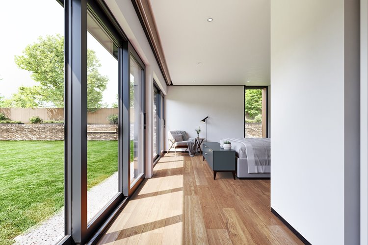
Bay Bow Windows Manufacturer China Foshan Factory Price Corner Post Cantilever Support Insulated Glass
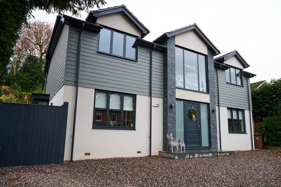
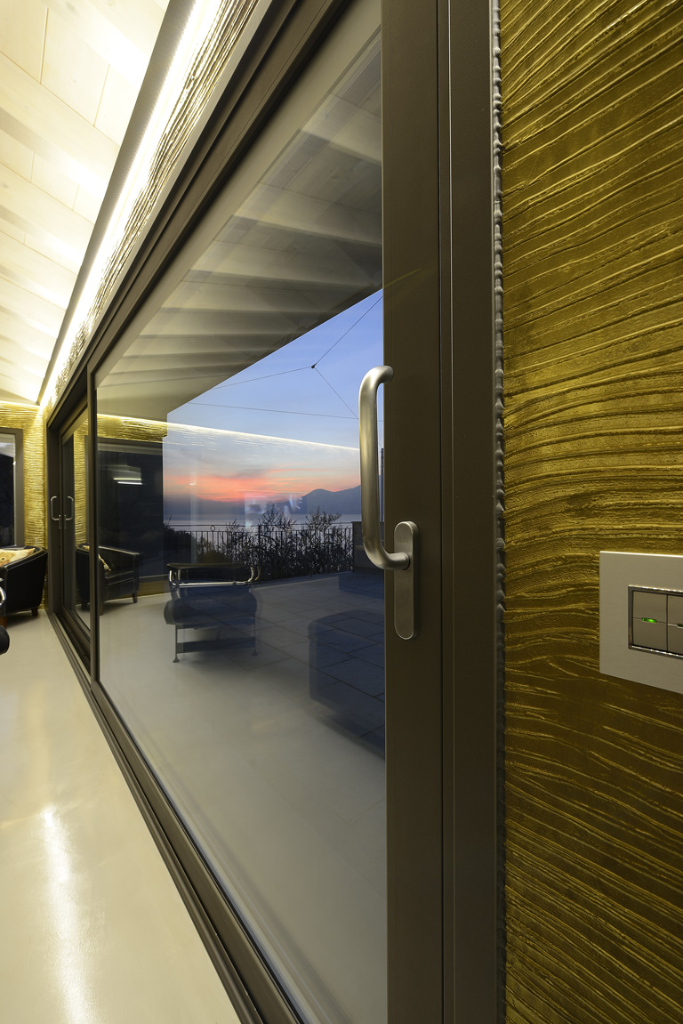
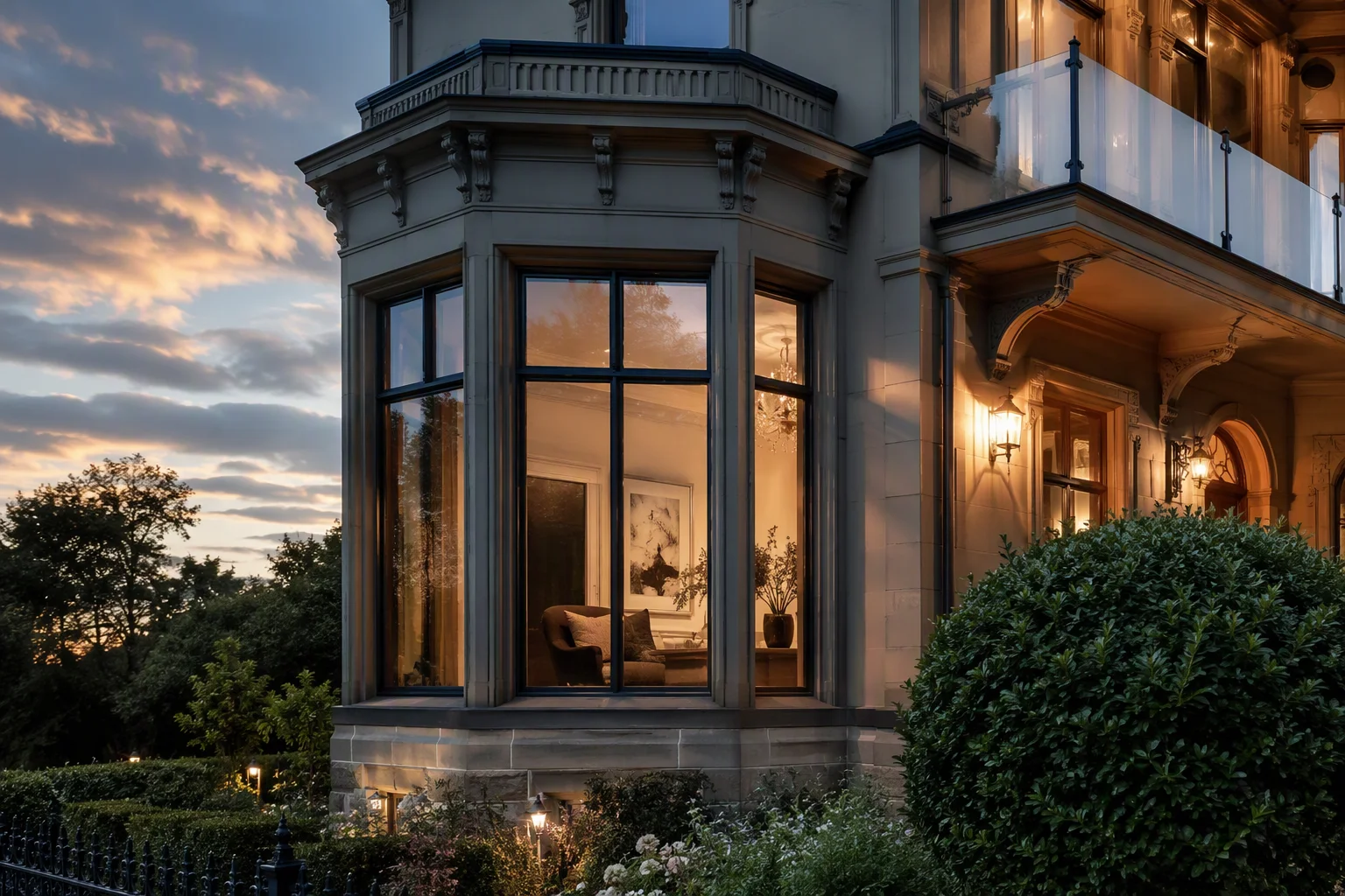
1. System Overview — The Bay Window Is a Small Building That Projects
A bay window is not a flat window assembly; it is a three-dimensional volume that projects from the facade, and it behaves structurally and thermally like the small building it is. Everything that governs flat windows still applies — glass sizing, frame strength, seals, hardware — but three questions appear that no flat window ever asks. First, the corner: where two angled faces meet, the corner post is not a joint trim but a structural member, because wind on a projection pushes on the angled faces sideways and tries to fold the bay flat against the wall. Second, the support: a volume that projects beyond the facade line must be held — from below by brackets or corbels, from above by suspension, or by a structural sill cantilevered from the opening — and the load path back into the building is a designed structure, not an afterthought. Third, the envelope: a projection has five or six faces exposed where the flat wall has one, a surface-to-volume ratio that makes it the coldest element of the facade and a condensation machine unless the thermal engineering is continuous through every corner, head and sill. Richocean manufactures bay and bow windows in Foshan, Guangdong, engineering the projection — corner posts, support strategy, angled-face glass and the six-sided thermal envelope — as one system in thermally broken 6063-T6 aluminium for the residential and hospitality markets where the bay is the building’s signature.
The format earns its permanence: the bay projects the room into the view, admits light from three directions where the flat wall admits it from one, and gives the facade the depth and shadow that make a building read as architecture. Those rewards are exactly why the engineering must be complete — a projection that folds under wind load, sags off its support, or streams condensation down its inside corners has failed as a building element, not merely as a window.
2. The Corner Post — The Member That Resists Folding
Wind does not treat a bay window politely. On a flat window, wind pushes perpendicular to the glass and the frame carries it into the opening. On a projection, wind arrives at the angled faces sideways — pushing them toward each other, trying to fold the bay flat against the facade — and perpendicular on the front face, trying to push the whole volume inward. The member that answers the folding load is the corner post: the vertical element where two angled faces meet. In a cheap assembly the corner is a trim joint — two frame ends mitred and screwed together, a cosmetic junction that happens to sit on the primary load path. In an engineered bay the corner post is designed as a structural member: its section is sized for the out-of-plane bending and the axial load the folding action imposes, its internal reinforcement — steel or aluminium core members where the calculation demands — carries the load the hollow section cannot, and its connections top and bottom transfer that load into the head and sill members and from there into the support and the building.
The corner post works as part of a frame, not alone: the head and sill rails of the projection tie the corners together, so the folding load on one angled face is shared across the volume and resolved into the facade at the support points. The connection details are where the design lives — mitred corners assembled on structural corner keys with the reinforcement continuous through the joint, anchorages sized for the combined wind and dead load, and the whole load path verified against ASTM E330 basis for the site’s design pressure with the projection’s geometry, not a flat window’s. The specification question that separates engineered bays from assembled ones is direct: show me the corner post’s load path — section, reinforcement, connections, and where the load lands in the building. An answer that stops at “strong profile” is not an answer.
3. Holding the Projection — Bracket, Suspension or Structural Sill
A bay window is a cantilevered volume, and every cantilever needs a load path back into the structure. Three strategies carry it, each with its own engineering and its own architecture. The bracket — a corbel or steel bracket under the bay’s sill, fixed to the facade below — is the classic: it carries the projection’s dead load plus live load plus the vertical component of wind straight down into the wall, and it reads externally as the traditional bracketed bay. The suspension hangs the projection from above: hangers or a support frame at the head transfer the load upward into the structure over the opening, which suits bays under eaves or balconies and keeps the facade below clean. The structural sill cantilevers the projection from the opening itself: the sill member is engineered as a beam anchored into the facade structure at the opening’s jambs, with no external bracket — the cleanest look and the most demanding calculation, because every kilogram of the projection and its glass lives in that anchorage.
Whichever strategy the architecture chooses, the engineering obligations are the same. The load schedule is complete: self-weight of frame and glass — insulating glass is heavy, and a three-face bay carries multiples of a flat window’s glass weight — plus the wind loads resolved through the projection geometry, plus any live load the sill invites (a person sitting in the bay is a design case the calculation must include where the format invites it). The anchorage is designed for the facade it lands in: masonry, concrete or steel each take their own fixings, edge distances and load spreads, and the fixing pattern is part of the window’s structural design, not the installer’s improvisation. And the head and sill members of the projection act as the tie that distributes the corner-post loads into the support points — which is why an engineered bay is specified as a system: corner posts, head and sill, support strategy and anchorage calculated together, because the projection stands or folds as one volume.
4. Angled Faces — Wind, Glass and Sightlines Off the Flat
The faces of a bay do not sit in the facade plane, and every consequence follows. Wind arrives at each angled face from a different direction with a different pressure coefficient — the front face takes the perpendicular pressure, the return faces take suction and side load — so each pane is sized to ASTM E1300 basis for the pressure its own face actually sees, not for the flat window’s. The angled geometry also changes the glass’s support condition: the panes meet at the corner posts at angles other than ninety degrees, the bite and edge support are set for the angled meeting, and where the format is a bow — the curved variant — the glass itself is curved to radius, heat-formed to the designed curve with the optical quality and the edge conditions the curve demands.
The sightlines carry the same discipline. The corner junction of two angled faces is the most visible joint on the building’s face, and it is also the joint that moves the most: the projection expands and contracts across its faces with solar gain, the corner takes the differential movement, and the joint detail must accommodate it without opening the seal or reading as a gap. Engineered corner details set the joint width to the movement calculation, carry the gaskets continuously round the corner, and keep the external sightline tight enough that the bay reads as one volume rather than three windows leaning together. On curved bows the discipline is radius consistency: the head, sill and glass all follow the same designed curve, and the fabrication tolerance on that curve is what keeps the bow reading as an arc rather than a polygon.
5. The Six-Sided Envelope — Thermal Engineering of a Projection
A flat window has one plane between inside and outside. A bay has five or six faces of envelope wrapped around one small volume of air — front, two returns, head, sill and often the roof of the projection — and that surface-to-volume ratio makes the bay the coldest element of the facade by geometry alone. The thermal engineering therefore cannot stop at the glazing: it has to be continuous through every element of the projection. The frames are thermally broken with PA66GF25 bars sized for the climate — and critically, the break runs continuously through the corner posts, because a corner that is broken in the faces but solid in the post is a thermal bridge shaped like the most exposed element of the bay. The head and sill of the projection are broken and insulated, the support bracket penetrations are thermally separated where they cross the envelope, and the underside of the bay’s sill — the face that looks up at the cold sky — is insulated, since warm interior air meets the coldest surface of the whole assembly there.
The condensation discipline follows the same logic as everywhere else and bites hardest here: every interior surface of the projection is kept above the dew point of the room air — glass inner pane through Low-E and argon-filled insulating units, frame surfaces through the break, and the inside corners through continuous insulation, because corners are where two cold surfaces meet and condensation starts first. The bay’s own geometry helps if it is used: the projection catches solar gain across three orientations, and the specification can place the glazing’s solar performance to turn that into passive warmth in the heating season while the shading strategy handles the summer. Where the format includes a bow, the curved head and sill carry the same continuous-break requirement around the curve — the thermal envelope of a projection has no flat faces to hide behind, and the engineering is only as continuous as its worst corner.
6. Performance Envelope — What a Bay & Bow System Is Rated Against
| Property | Standard | Design Basis |
|---|---|---|
| Structural — projection | ASTM E330 basis | Corner post section and reinforcement, head/sill tie members, support anchorage, complete load path for folding and perpendicular wind |
| Glass sizing per face | ASTM E1300 | Each angled face sized to its own pressure coefficient; curved glass to the bow radius with its own support conditions |
| Support loads | Structural calculation | Dead load of frame and glass, live load where the format invites it, wind components, anchorage designed for the facade substrate |
| Air permeability | EN 12207 / ASTM E283 | Compression seals through every corner and joint, gasket continuity round angled junctions, movement-accommodating corner details |
| Watertightness | EN 12208 / ASTM E547 | Drained and ventilated sills on every face, projection roof drainage, weep paths that work on angled planes |
| Thermal transmittance | U-value (ISO 10077 basis) | Continuous PA66GF25 break through faces, corner posts, head and sill; insulated sill underside; Low-E argon units |
| Condensation resistance | Surface temperature / CR basis | Every interior surface above dew point; inside corners continuously insulated |
| Corrosion | Corrosion category to site | SS316 fixings, brackets and hardware, rated coatings for C5-M exposure — the projection’s underside sees weather the flat facade never does |
7. Bay, Bow and Box — The Projection Formats Compared
| Aspect | Bay (Faceted) | Bow (Curved) | Box Bay (Orthogonal) |
|---|---|---|---|
| Geometry | Three or more flat faces at set angles — commonly 30 or 45 degrees | Curved front, glass and rails heat-formed to radius | Flat front, ninety-degree returns |
| Corner engineering | Angular corner posts — structural members at each facet junction | Continuous curve — no corners, but radius consistency across head, sill and glass | Ninety-degree posts — simplest load path, largest sightline |
| Glass | Flat panes per face, sized per face pressure | Curved, heat-formed — premium process, optical quality specified | Flat panes |
| Movement joints | At each facet corner — widths set by movement calculation | Distributed along the curve | At two corners |
| Support | Bracket, suspension or structural sill per architecture | Continuous support along the curve — brackets or a continuous bearer | Bracket or structural sill |
| Reads as | Faceted jewel — shadow lines at each facet | Smooth arc — the premium of the three | Crisp volume — modern and direct |
8. Technical FAQ
Because wind loads a projection differently from a plane. On a flat window the pressure is perpendicular and the frame carries it into the opening. On a bay, wind hits the angled faces sideways and tries to fold the volume flat against the wall, and hits the front face trying to push it in — and the member that resists that folding is the corner post where the faces meet. In a cheap assembly the corner is a mitred trim joint sitting, unknowingly, on the primary load path; in an engineered bay the post’s section, internal reinforcement and its connections into head and sill are calculated for the folding and perpendicular loads and verified to ASTM E330 basis. The specification test is one sentence: show the corner post’s load path, and where the load lands in the building.
By the architecture and the facade’s ability to carry load. Brackets — corbels or steel brackets under the sill — carry everything straight down into the wall below and read externally as the traditional bracketed bay; they need sound substrate below. Suspension hangs the projection from the structure above — right for bays under eaves or balconies, keeping the facade below clean. The structural sill cantilevers the whole volume from the opening’s jambs with no external bracket — the cleanest look and the most demanding calculation, since every kilogram of frame, glass and any live load the format invites lives in that anchorage. Whichever is chosen, the load schedule must be complete — self-weight, wind components resolved through the projection geometry, live load where a person could sit — and the anchorage designed for the actual substrate, with fixings, edge distances and load spread as part of the window’s structural design, not site improvisation.
Geometry. A projection wraps five or six faces of envelope around one small air volume — the highest surface-to-volume ratio on the facade — and the inside corner is where two cold surfaces meet, so it is the first place the room’s dew point is reached. The engineering answer is continuity: the PA66GF25 thermal break runs through the faces AND through the corner posts — a bay broken in the faces but solid at the corners is a thermal bridge shaped like its most exposed element — the head and sill are broken and insulated, the sill underside that looks at the cold sky is insulated, bracket penetrations are thermally separated, and every interior surface is kept above the dew point by calculation. A bay that sweats at its corners is telling the truth about a break that stopped short.
Different enough to specify separately. The faceted bay concentrates its structure at discrete corner posts; the bow distributes the same demands along a continuous curve. Its glass is heat-formed to radius — a premium process with its own optical-quality specification, because a curve shows every deviation a flat pane would hide. Its head and sill rails follow the same designed curve, and the fabrication tolerance on that radius is what makes the bow read as an arc rather than a polygon. Structurally the bow needs continuous support along the curve — a run of brackets or a continuous bearer — instead of point supports at corners, and its movement joints are distributed along the curve rather than at facet corners. Thermally the continuous-break requirement runs around the curve with no flat faces to hide behind. Both formats reward the same discipline — the projection engineered as a volume — but the bow pays a fabrication premium for the privilege of having no corners at all.
9. China Market Positioning — Why Foshan, Why Richocean
A bay or bow window is a fabrication-intensive system: angled or curved geometry, structural corner engineering, support steel and a six-sided thermal envelope all have to arrive as one coordinated set. Foshan in Guangdong concentrates the chain that builds it: 6063-T6 extrusion with the tooling for projection head, sill and corner-post sections, CNC machining for the angled junctions the geometry demands, steel reinforcement and bracket fabrication, heat-formed glass lines for bow radii, PA66GF25 thermal breaks and insulating-glass lines for the envelope, and the SS316 and rated-coating hardware the projection’s exposed underside needs. Richocean builds bay and bow windows in Foshan for residential, heritage-replacement and hospitality projects across Europe, North America, the Middle East and Southeast Asia, calculating the projection — corner posts, support strategy, per-face glass and the continuous break — as one system and shipping it as one coordinated set with the anchorage schedule included.
10. Example Applications
Illustrative configuration; not a quoted project. A European heritage-replacement townhouse specifying a three-facet bay at forty-five degrees on the first-floor front elevation: structurally reinforced corner posts calculated for the site wind pressure with the folding and perpendicular components resolved through the projection, steel brackets under the sill anchored into the masonry facade with the fixing pattern scheduled, PA66GF25 breaks continuous through faces, corners, head and sill, insulated sill underside, Low-E argon insulating glass sized per face to ASTM E1300 basis, and interior surface temperatures verified above the room dew point. The controlling decisions are the corner-post load path, the bracket anchorage into heritage masonry, and the thermal continuity through the corners that keeps the projection’s inside faces dry.
Illustrative configuration; not a quoted project. A coastal resort lounge specifying a curved bow projection over the sea view: heat-formed laminated glass to the designed radius with optical quality specified for the curve, continuous bearer support along the bow with SS316 fixings in the C5-M corrosion category, continuous thermal break around the curved head and sill rails, movement joints distributed along the curve, and every face’s glass and support checked for the exposed marine wind regime. Here the controlling decisions are the radius consistency across glass, head and sill, the corrosion category driving the entire support and fixing schedule, and the envelope continuity around a curve that has no corners to hide a break.
11. Price Drivers — What Actually Moves the Cost
On a projection the cost follows geometry and structure. The corner engineering comes first: reinforced posts, structural corner keys and the calculation behind them cost multiples of a mitred trim joint — and they are the difference between a bay that stands and one that folds. The support strategy is next: brackets and their anchorage, suspension hangers, or a structural sill engineered as a beam — each with its own fabrication and its own fixing schedule into the facade. Then the glass: per-face sizing to the pressure each angled face sees, and on bows the heat-forming premium for curved laminated or insulating units. The thermal envelope adds the continuous break through faces, corners, head, sill and the sill underside, plus the insulated panels that close the projection. Finish and hardware follow the exposure — the projection’s underside sees weather the flat facade never does, so coatings and SS316 fixings are specified for the site’s corrosion category. Certification and shipping complete the picture: a bay ships as a coordinated set, often pre-assembled by face, with the anchorage schedule and installation sequence documented. The specification discipline is to spend where the projection’s physics lives — corners, support and envelope continuity — because those are the three places a cheap bay fails. Indicative ranges only, not offers; final pricing depends on the specification, the geometry and the volume.
12. Installation, Commissioning and Maintenance
Installation of a projection is structural work before it is glazing work. The facade substrate is verified against the anchorage schedule — the bracket or suspension points land where the calculation says, with the edge distances and load spreads the substrate can actually take. The support is set level and fixed, the projection’s sill and head members are tied to the support and to the opening, and only then are the faces and corner posts assembled plumb and in-plane — a corner out of plumb is not a sightline defect but a load-path defect, since the folding forces assume the geometry that was calculated. Glass is set per face with the bite and edge support the angled junctions require, seals are run continuously round every corner, and the drained sills and projection roof are verified to shed outward. Commissioning checks the whole volume: plumb and level of every face and corner, operation of any vent units the projection includes, compression witness on every seal including the corner junctions, and the weep paths on each face and the projection roof. Maintenance is scheduled and small: annual inspection of brackets and fixings — the projection’s most exposed steel — cleaning and clearing of every sill and roof drain, seal inspection at the corners where movement concentrates, and hardware service on the vent units. The bracket and anchorage inspection is the one the format adds to every other window’s list, and it is the one that keeps the cantilever honest for decades.
13. 360° Service and the Richocean Engineering Philosophy
Richocean works from drawing to delivery on every projection: the project states its geometry — facet angles or bow radius, projection depth, face sizes — its climate, its exposure and its facade substrate; Richocean calculates the volume as one system: corner-post sections and reinforcement, head and sill tie members, the support strategy and its anchorage schedule, per-face glass to the pressure each face sees, and the six-sided thermal envelope with the break continuous through every corner. OEM and ODM service covers custom facet geometries, bow radii, heritage-matching profiles and the coordinated shipping of projection sets with their installation sequences. The founding philosophy fits the bay and bow exactly, because a projection is the one window format that is also a piece of architecture: it leaves the facade, it hangs in the weather, and it carries its loads back into the building through paths that must be drawn, calculated and built — not assumed. Engineering the volume, not the view, is the only honest way to build a projection, and it is the standard every Richocean bay and bow is built against.
14. Conclusion — The Projection Is the Product; the Volume Is the Engineering
A bay or bow window sells the room an extra dimension: light from three directions, the view wrapped around, the facade given depth and shadow. Delivering it is volumetric engineering — corner posts designed as the structural members that resist folding, a support strategy whose load path is calculated back into the building, per-face glass sized to the wind each angled face actually sees, and a thermal break continuous through every face, corner, head and sill so the projection’s six-sided envelope stays warm and dry. The format has no flat places to hide: every corner is a load path, every face is a wind case, every surface is an envelope. Richocean manufactures bay and bow windows in Foshan, Guangdong, calculating the projection as one volume and shipping it as one coordinated set. For a bay or bow specification, a projection-geometry study for your elevation, or a project quotation, send the geometry, the facade substrate and the site exposure — the volume will be built to stand, to stay warm, and to hold the view it was drawn for.